11
Reference Manual
IP2048/RM, Rev AA
Section 3: Installation
February 2015
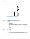
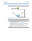
3. In tanks with rounded or conical bottoms, mount the transmitter off-center. If needed,
a perforated reflector plate can be installed on the tank bottom directly under the
transmitter center line to ensure a satisfactory return echo.
4. Avoid detecting pump casings, as the liquid falls away, by not mounting the transmitter
directly above pumps. If this is not possible, fine-tuning of the transmitter on-site may
be required.
3.3.3 Mounting the transmitter above the liquid surface
A 2-in. thread is provided to mount the transmitter. The thread form is either BSPT or NPT, and is
clearly marked on the hexagon of the transmitter body.
Note
The Mobrey MSP400RH and MSP900GH are designed to be mounted in a non-metallic
fitting or flange. The use of metallic fittings/flanges is not recommended.
To help installation, flange accessories and bracket kits are available from Emerson Process
Management (see Product Data Sheet IP2045 for accessory part numbers). The accessory
flanges supplied are manufactured from PVC and are a full face design. Care must be taken
when installing to raised face mating flanges on the tank or vessel to prevent distortion of the
PVC flange by over-tightening the bolts.
Bracket mounting
The bracket kit contains a stainless steel angle bracket and PVC threaded disc, which may be
used to mount the transmitter on a support over the liquid surface. See Product Data Sheet
IP2045 for accessory part numbers.
The bracket and disc dimensions are in Figure A-4 on page 69. The combined weight of bracket
and disc is 16 oz (0,5 kg). For transmitter weight, see “Specifications” on page 63.
Bracket installation procedure
1. Attach bracket to the disc using the three screws provided.
2. Attach the assembled bracket and disc to a rigid support over the liquid surface. The
bracket may be bolted to a suitable crossmember (structural section of steel).
3. Use PTFE tape on the screw thread (Figure 3-3 on page 13).
4. Insert the transmitter into the disc.
5. Tighten to a torque of 1.5 lbf.ft. (2 Nm) using the hexagon. Do not use the transmitter
housing to tighten.


