117
Reference Manual
IP2048/RM, Rev AA
Appendix F: Configuring Using HART
February 2015
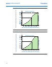
Flumes that deviate from the standard “3/2 power law”, e.g. round-bottomed flumes, must use
the “Special Plot” profile option that is based on flow versus height tabulations (see
page 112).
Setting-up procedure for “Flume/Weir-3/2”:
1. Use parameter Tank Shape/NLP (P011) to select “Flume/Weir-3/2”.
2. Enter the scale factor into the PV Scale Factor parameter (page 121).
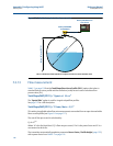
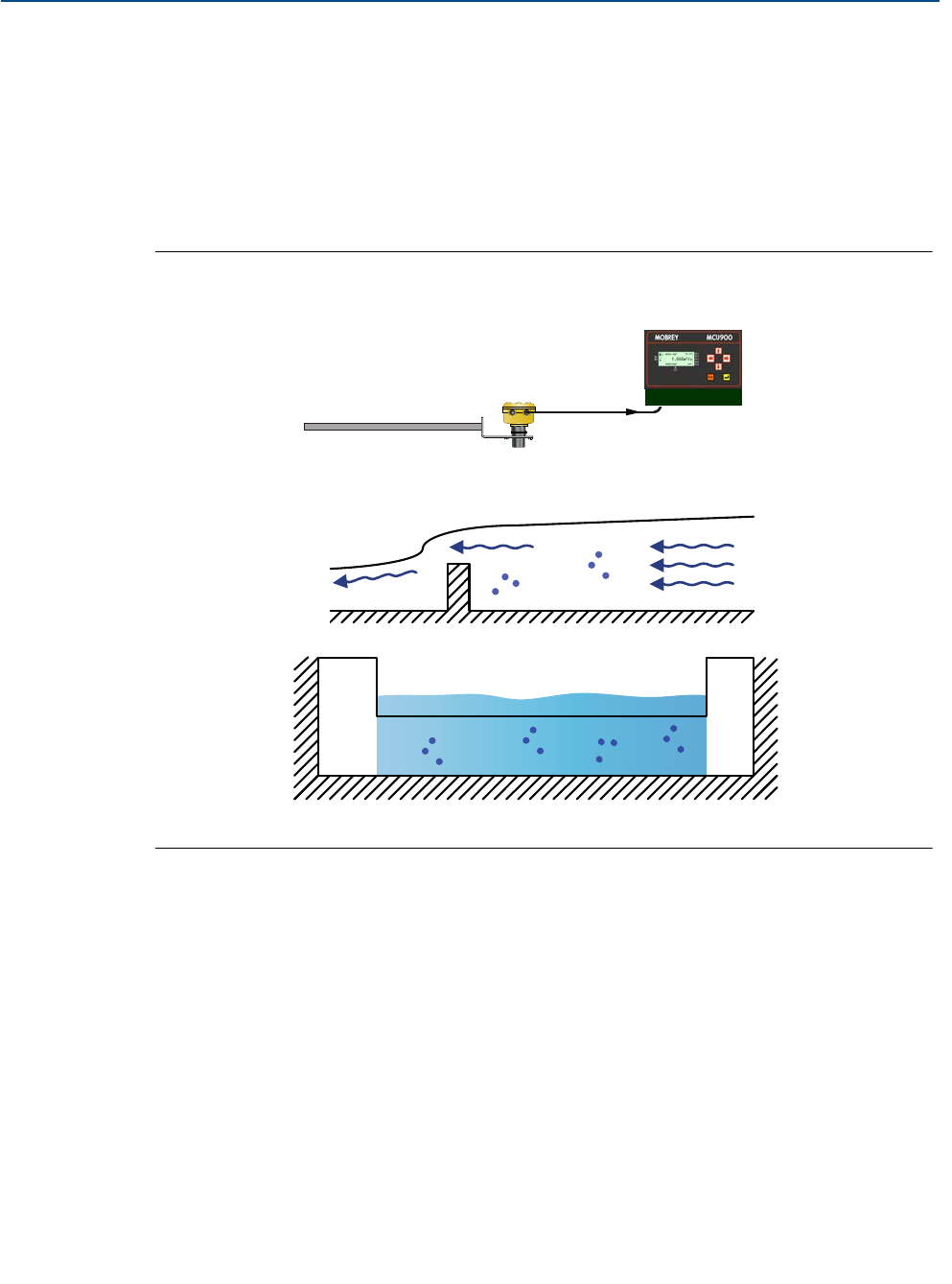
Figure F-6. Rectangular weir cross-section
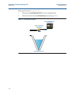
Tank Shape/NLP (P011) = “V-Notch-5/2”
This setting is applicable when flow measurements are needed from an open channel with a
V-notch profile.
The rate of flow through a V-notch is calculated using:
Q = k x h
Pwr
Where ‘h’ is the live liquid level, ‘Q’ is flow rate per second, ‘Pwr’ is the power factor, and ‘k’ is a
user-entered scale factor.
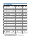
The transmitter automatically populates parameter Power Factor / Profile Height (page 122)
with a power factor from Table F-1 on page 119.
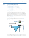
4–20 mA/HART
Mobrey MSP400RH
or MSP900GH
Side
View
End View Downstream
Mobrey MCU900 Series
Control Unit


