13
Reference Manual
IP2048/RM, Rev AA
Section 3: Installation
February 2015
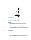
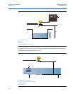
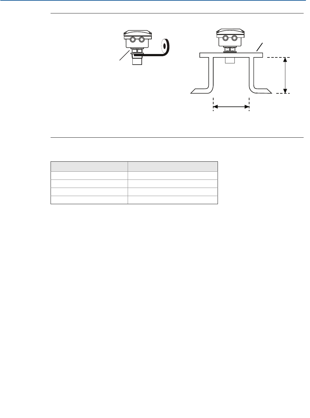
Figure 3-3. Mounting the transmitter using a nozzle/stand-off
D. See dimension D in Table 3-1.
L. See dimension L in Table 3-1.
Table 3-1. Nozzle diameter size and maximum length
3.3.4 Open channel flow installations
There are normally two distinct parts to an open channel flow measurement system; the
primary element (flow structure) and the secondary element (Head measurement instrumenta-
tion). For accurate open channel flow measurement, both parts of the system must be correctly
installed.
This section explains the important parts of installing the transmitter (secondary element). The
flow structure (primary element) installation can be referenced in the British (BS3680) or ISO
International standards.
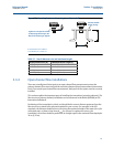
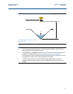
Positioning of the transmitter is critical, and should be the correct distance upstream from the
flow structure as stated in the relevant standard for your country. For example, in the ISO
standards, the distance should be four to five times the maximum height of the water (H
max
) for
a thin plate weir, or three to four times H
max
for a flume. For optimum accuracy, the
transmitter’s front face should be positioned at a height equal to the maximum flow depth plus
14 in. (0,35 m).
Nozzle Diameter Size (D) Maximum Nozzle Length (L)
DN50 (2 in.) 4 in. (100 mm)
DN80 (3 in.) 6.3 in. (160 mm)
DN100 (4 in.) 6.3 in. (160 mm)
DN125 (5 in.) 11.8 in. (300 mm)
PTFE
L
D
Tighten To A Torque Of 1.5 lbf.ft.
(2 Nm) Using The Hexagon. Do
Not Use The Housing To Tighten
Use Non-metallic
Fitting / Flange


