17
Reference Manual
IP2048/RM, Rev AA
Section 3: Installation
February 2015
3.4.2 Connecting the cable wires to the MSP400RH
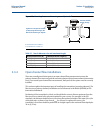
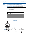
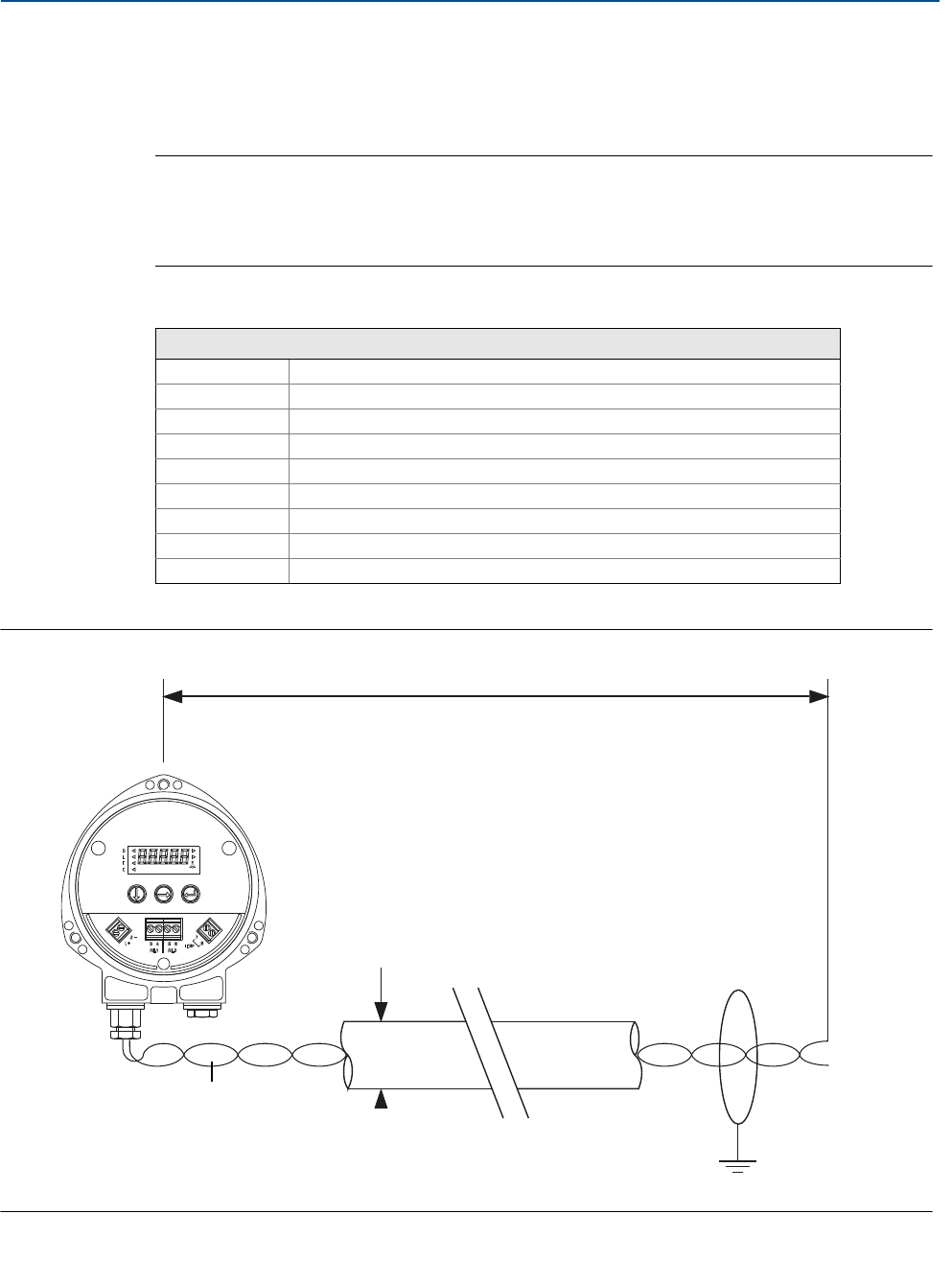
Connect the cable wires to the transmitter as shown in Figure 3-7. See also “Wiring to allow
HART communications” on page 19 if HART digital communications is required.
Note
Make sure the power supply is off when connecting the transmitter.
The MSP400RH is not intrinsically safe, and is for use in non-hazardous (ordinary
location) installations only.
Table 3-2. Terminal connections on the MSP400RH
Figure 3-7. Wiring Diagram for The MSP400RH
Connections
Terminal 1 24 Vdc
Terminal 2 0 Vdc
Terminal 3 RL1 (SPST) - see “Relays” on page 18
Terminal 4 RL1 (SPST) - see “Relays” on page 18
Terminal 5 RL2 (SPST) - see “Relays” on page 18
Terminal 6 RL2 (SPST) - see “Relays” on page 18
Terminal 7 Remote temperature sensor (if used) - see page 19
Terminal 8 Remote temperature sensor (if used) - see page 19
Earth Screen Connect the cable shield/screen to ground (earth) in the control room
Min. 12 Vdc
Ø4 to 8 mm
(0.15 to 0.31 in.)
Twisted-pair, Screened
Min. 0.22mm
2
(24 SWG / 23 AWG)
Max. 1.5mm
2
(16 SWG / 18 AWG)
0 Vdc
Max. 3000 m (9750 ft.)
+12 to 30 Vdc


