


Chapter 4 Explanation of Functions
4 - 72
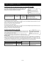
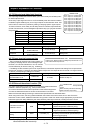
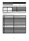
4.2.78 Output signal delay/hold function
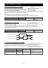
The output signal delay/hold function allows you to set on-delay and off-delay times
for each output terminal.
Since every output signal is turned on or off immediately when the relevant condition
is satisfied, signal chattering may occur if signal outputs conflict with each other. Use
this function to avoid such a problem by holding or delaying specific signal outputs.
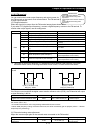
To use this function, set on-delay and off-delay times for individual output terminals
(a total of six terminals, such as intelligent output terminals [11] to [15] and the alarm
relay terminal).
Output terminal On-delay time Off-delay time
11 C130 C131
12 C132 C133
13 C134 C135
14 C136 C137
15 C138 C139
RY(AL*) C140 C141
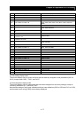
Item Function code Range of data Description
Output on
C130/C132/C134/
C136/C138/C140
0.0 to 100.0 (s) Setting of on
Output off
C131/C133/C135/
C137/C139/C141
0.0 to 100.0 (s) Setting of off
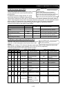
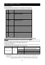
4.2.79 Input terminal response time
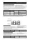
- The input terminal response time function allows you
to specify a sampling time for each of intelligent input
terminals 1 to 8 and the FW terminal. You can use this
function effectively to remove noise (e.g., chattering).
- If chattering hinders constant input from an input terminal, increase the response time setting for the input terminal.
Note that an increase in response time deteriorates the response. The response time can be set in a range of about 2
to 400 ms (corresponding to settings of 0 to 200).
Item Function code Range of data Description
Response time of intelligent
input terminals 1 to 8
C160-C167
FW terminal response time C168
0. to 200. Variable in step of 1
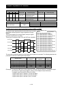
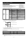
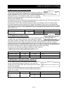
4.2.80 External thermistor function (TH)
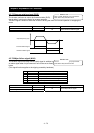
The external thermistor function allows you to connect an external thermistor
installed in external equipment (e.g., motor) to the inverter,
and use the thermistor for the thermal protection of the external equipment.
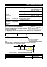
Connect the external thermistor to control circuit terminals TH and CM1.
Make the functional settings according to the thermistor specifications as described below.
When using this function, the wiring distance between the inverter and motor must be 20 m or less. Since the
thermistor current is weak, isolate the thermistor wiring to the inverter from other wirings appropriately to prevent the
thermistor signal from being affected by the noise caused by other signal currents, including the motor current.
Item Function code Range of data Description
00 Disabling the external thermistor (TH) function
01
Enabling the TH function (resistor element with
a positive temperature coefficient [PTC])
Thermistor for thermal
protection control
b098
02
Enabling the TH function (resistor element with
a negative temperature coefficient [NTC])
Thermal protection level
setting
b099 0 to 9999. (Ω)
Setting of the thermal resistance level
(according to the thermistor specifications) at
which to trigger tripping
Thermistor input tuning C085 0.0 to 1000. Setting for gain adjustment
Note: Specifying "01" for the thermistor for thermal protection control (b098) without an external thermistor
connected makes the inverter trip.
C130: Output 11 on-delay time
C131: Output 11 off-delay time
C132: Output 12 on-delay time
C133: Output 12 off-delay time
C134: Output 13 on-delay time
C135: Output 13 off-delay time
C136: Output 14 on-delay time
C137: Output 14 off-delay time
C138: Output 15 on-delay time
C139: Output 15 off-delay time
C140: Output RY on-delay time
C141: Output RY off-delay time
Related code
b098: Thermistor for thermal protection
control
b099: Thermal protection level setting
C085: Thermistor input tuning
Related code
C160 to C167: Response time of intelligent input terminals 1 to 8
C168: FW terminal response time
Related code