


Chapter 4 Explanation of Functions
4 - 118
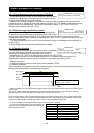
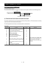
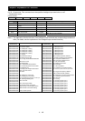
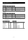
(iii) 02, 12 command: This command turns the specified intelligent input terminals on or off.
- Transmission frame
Frame format
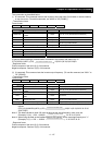
STX Station No. Command Data BCC CR
Description Data size Setting
STX Control code (Start of TeXt) 1 byte STX (0x02)
Station No.
Station number of control-target
inverter
2 bytes 01 to 32, or FF (broadcast to all stations)
Command Command to be transmitted 2 bytes 02
Data Data to be transmitted 16 bytes See Note 5.
BCC Block check code 2 bytes
XOR of the items from "Station No." to "Data."
See Item (3) of this section.
CR Control code (Carriage Return) 1 byte CR (0x0D)
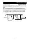
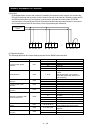
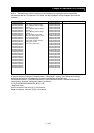
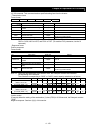
Note 5: The table below lists the functions of the intelligent input terminals and corresponding hexadecimal
data. (For details, see the explanation of the intelligent input terminal functions.)
Data
(hexadecimal)
Description
Data
(hexadecimal)
Description
0000000000000001
0000000000000002
0000000000000004
0000000000000008
0000000000000010
0000000000000020
0000000000000040
0000000000000080
0000000000000100
0000000000000200
0000000000000400
0000000000000800
0000000000001000
0000000000002000
0000000000004000
0000000000008000
0000000000010000
0000000000020000
0000000000040000
0000000000080000
0000000000100000
0000000000200000
0000000000400000
0000000000800000
0000000001000000
0000000002000000
0000000004000000
0000000008000000
0000000010000000
0000000020000000
0000000040000000
0000000080000000
FW: Forward rotation
RV: Reverse rotation
CF1: Multispeed 1 setting
CF2: Multispeed 2 setting
CF3: Multispeed 3 setting
CF4: Multispeed 4 setting
JG: Jogging
DB: External DC braking
SET: Set 2nd motor data
2CH: 2-stage acceleration/deceleration
-
FRS: Free-run stop
EXT: External trip
USP: Unattended start protection
CS: Commercial power source enable
SFT: Software lock
AT: Analog input voltage/current select
SET3: 3rd motor control
RS: Reset
-
STA: Starting by 3-wire input
STP: Stopping by 3-wire input
F/R: Forward/reverse switching by 3-wire input
PID: Enabling/disabling PID
PIDC: PID reset
-
CAS: Control gain setting
UP: Remote control UP function
DWN: Remote control DOWN function
DWN: Remote control data clearing
-
OPE: Forcible operation
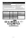
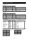
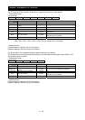
0000000100000000
0000000200000000
0000000400000000
0000000800000000
0000001000000000
0000002000000000
0000004000000000
0000008000000000
0000010000000000
0000020000000000
0000040000000000
0000080000000000
0000100000000000
0000200000000000
0000400000000000
0000800000000000
0001000000000000
0002000000000000
0004000000000000
0008000000000000
0010000000000000
0020000000000000
0040000000000000
0080000000000000
0100000000000000
0200000000000000
0400000000000000
0800000000000000
1000000000000000
2000000000000000
4000000000000000
8000000000000000
SF1: Multispeed bit 1
SF2: Multispeed bit 2
SF3: Multispeed bit 3
SF4: Multispeed bit 4
SF5: Multispeed bit 5
SF6: Multispeed bit 6
SF7: Multispeed bit 7
OLR: Overload restriction selection
TL: Enabling /disabling torque limitation
TRQ1: Torque limit selection bit 1
TRQ2: Torque limit selection bit 2
PPI: P/PI mode selection
BOK: Braking confirmation
ORT: Orientation
LAC: LAD cancellation
PCLR: Clearance of position deviation
STAT: Pulse train position command input enable
-
ADD: Trigger for frequency addition
F-TM: Forcible-terminal operation
ATR: Permission of torque command input
KHC: Cumulative power clearance
SON: Servo On
FOC: Forcing
MI1: General-purpose input 1
MI2: General-purpose input 2
MI3: General-purpose input 3
MI4: General-purpose input 4
MI5: General-purpose input 5
MI6: General-purpose input 6
MI7: General-purpose input 7
MI8: General-purpose input 8