


Chapter 2 Installation and Wiring
2 - 13
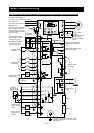
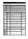
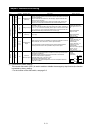
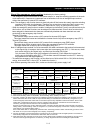
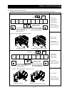
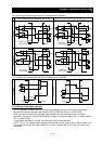
(2) Layout of main circuit terminals
The figures below show the terminal layout on the main circuit terminal block of the inverter.
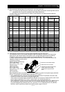
Terminal layout Inverter model
SJ700-055 to
SJ700-075LFF2
SJ700-055 to
SJ700-075HFF2
R0 and T0: M4
Ground terminal: M6
Other terminals: M6
RB
R
(L1)
S
(L2)
T
(L3)
PD
(+1)
P
(+)
N
(-)
U
(T1)
V
(T2)
W
(T3)
R0 T0
G G
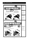
SJ700-110LFF
SJ700-110HFF
R0 and T0: M4
Ground terminal: M6
Other terminals: M6
SJ700-150 to
SJ700-185LFF
SJ700-150 to
SJ700-220HFF
R0 and T0: M4
Ground terminal: M6
Other terminals: M6
RB
R
(L1)
S
(L2)
T
(L3)
PD
(+1)
P
(+)
N
(-)
U
(T1)
V
(T2)
W
(T3)
R0 T0
G G
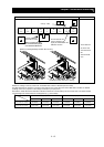
SJ700-220LFF
R0 and T0: M4
Ground terminal: M6
Other terminals: M8
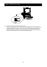
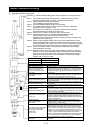
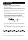
Disabling the EMC filter (factory setting)
[Method of enabling/disabling the EMC filter function]
Enabling the EMC filter
Charge
lamp
Jumper
connecting
terminals PD and P
Ground
terminal
with
jumper
(shaded in the
figure) to enable/disable the
EMC filter function
When
not
using
the
DCL
,
do not remove the jumper
from terminals PD and P.
Disabling the EMC filter (factory setting)
[Method of enabling/disabling the EMC filter function]
Enabling the EMC filter
Jumper
connecting
terminals PD and P
Ground
terminal
with
jumper
(shaded in the
figure) to enable/disable the
EMC filter function
When
not
using
the
DCL
,
do not remove the jumper
from terminals PD and P.