


Chapter 6 Maintenance and Inspection
6 - 2
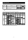
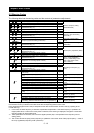
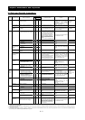
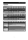
6.2 Daily and Periodic Inspections
Inspection cycle
Periodic
Part to
inspect
Inspection item Detail of inspection
Daily
Annual Biennial
Inspection method Criterion Test equipment
Environment Check the ambient temperature,
humidity, and dust.
{
See Section 2.1, "Installation." The ambient temperature must
be within -10°C to +50°C without
congelation. The ambient
humidity must be 90% RH or less
without condensation.
Thermometer,
hygrometer,
recorder
Whole inverter Check for abnormal vibrations and
noise.
{
Check visually and by listening. There must be no abnormality
found.
General
Power supply
voltage
Check that the main circuit voltage
is normal. {
Measure the voltage between the
main circuit terminals R, S, and T.
The measured voltage must be
within the allowable tolerance for
AC power voltage.
Tester, digital
multimeter
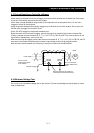
(1) Check the ground resistance
between the main circuit and
ground terminals with a megger.
{
Disconnect all input and output cables
from the inverter's main circuit terminal
block, detach the control circuit terminal
block from the inverter, and remove the
jumper for switching the inverter's
internal filter function. Subsequently,
measure the insulation resistance
between the ground terminal and the
jumper connecting all the following
terminals:
R, S, T, U, V, W, P, PD, N, RB, R0, and
T0
The measured ground resistance
must be 5MΩ or more.
500 VDC class
megger
(2) Check screws and bolts for
loosening.
{
Retighten loose screws and bolts. There must be no abnormality
found.
General check
(3) Check each part for any trace of
overheating.
{
Check visually. There must be no abnormality
found.
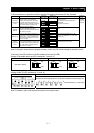
(1) Check the conductors for
distortion.
{
Connecting
conductors and
cables
(2) Check the cable insulations for
damage.
{
Check visually
There must be no abnormality
found.
Terminal block Check the terminal blocks for
damage.
{
Check visually There must be no abnormality
found.
Inverter circuit
and converter
circuit (including
resistors)
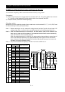
Check the resistance between
terminals.
{
Remove all cables from the
inverter's main circuit terminal block.
Use a tester (in 1Ω range mode) to
measure the following:
- Resistance between terminals R,
S, and T and terminals P and N
- Resistance between terminals U,
V, and W and terminals P and N
See Section 6.5, "Method of
Checking the Inverter and
Converter Circuits." Standard
operating life of inverter circuit
until replacement: 106 cycles of
starting and stopping (*3)
Analog tester
(1) Check for liquid leak. { Smoothing
capacitor
(2) Check that the relief valve does
not protrude or swell.
{
Check visually. There must be no abnormality
found.
Target operating life until
replacement: 10 years
(*1) (*3)
Capacitance
meter
(1) Check that no fluttering sound is
generated during the relay
operation.
{
Check by listening.
There must be no abnormality
found.
Main
circuit
Relay
(2) Check the contacts for damage.
{
Check visually. There must be no abnormality
found.
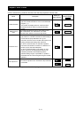
(1) While performing a unit
operation of the inverter, check
the balance output voltage
among the individual phases.
{
Measure the voltage between the
cables connected to the main circuit
terminals U, V, and W.
The inter-phase voltage balance
must be as follows:
200 V class models: 4 V or less
400 V class models: 8 V or less
Control
and
protective
circuits
Operation
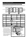
(2) Carry out a sequential
protection operation test, and
check the protective and display
circuits for any abnormality.
{
Short-circuit or open the protective
circuit outputs as a simulation. An error must be detected
according to the sequence.
Digital
multimeter,
rectifier
instrument, and
voltmeter
(1) Check for abnormal vibrations
and noise
{
Turn the fan manually during the
inverter power-off status.
Cooling fan
(2) Check the joints for loosening.
{
Check visually.
The fan must rotate smoothly.
There must be no abnormality
found.
Standard operating life until
replacement: 10 years
(*2) (*3)
Cooling
system
Heat sink Check for clogging.
{
Check visually. The heat sink must not be
clogged.
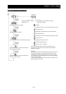
(1) Check that all LEDs light up
normally.
{
Check visually.
The LEDs must light up normally.
Monitor
(2) Clean the monitor. { Clean the monitor with a rag.
Display
Meter Check that meter readings are
normal.
{
Check the meter readings on the
panel.
The readings must meet the
standard and control values.
Voltmeter and
ammeter
(1) Check for abnormal vibrations
and noise. {
Check vibrations and noise visually,
by listening, and with physical
senses.
There must be no abnormality
found.
General
(2) Check for unusual smells.
{
Check for any unusual smells
caused by overheating or damage.
There must be no abnormality
found.
Motor
Insulation
resistance
Check the ground resistance
between all motor terminals and the
ground terminal with a megger.
{
Remove the cables from the
inverter's main circuit terminals U, V,
and W, connect the motor wires (for
three phases) with one another, and
measure the ground resistance
between the motor wires and the
ground terminal.
The measured ground resistance
must be 5MΩ or more.
500 VDC class
megger
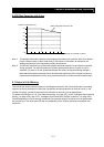
*1 The operating life of the smoothing capacitor is under the influence of the ambient temperature. Refer to Section 6.6, "Smoothing-Capacitor Life Curve," as a standard for the
operating life until replacement.
*2 The operating life of the cooling fan varies depending on environmental conditions, including the ambient temperature and dust. Check the status of the cooling-fan operation
during daily inspections.
*3 The standard operating life (number of years or operation cycles) and the data described in Section 6.6, "Smoothing-Capacitor Life Curve," are based on the expected design
life, but they do not indicate the guaranteed life of any parts.