


Chapter 2 Installation and Wiring
2 - 7
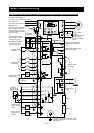
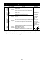
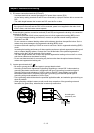
(1) Explanation of main circuit terminals
Symbol Terminal name Description
R, S, T
(L1, L2, L3)
Main power input
Connect to the AC power supply.
Leave these terminals unconnected when using a regenerative converter (HS900 series).
U, V, W
(T1, T2, T3)
Inverter output Connect a 3-phase motor.
PD, P
(+1, +)
DC reactor connection
Remove the jumper from terminals PD and P, and connect the optional power factor reactor
(DCL).
P, RB
(+, RB)
External braking
resistor connection
Connect the optional external braking resistor.
(The RB terminal is provided on models with 22 kW or less capacity.)
P, N
(+, -)
Regenerative braking
unit connection
Connect the optional regenerative braking unit (BRD).
G
Inverter ground
Connect to ground for grounding the inverter chassis by type-D grounding (for 200 V class
models) or type-C grounding (for 400 V class models).
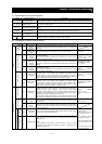
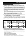
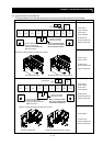
(2) Explanation of control circuit terminals
Symbol
Terminal name
Description Electric property
L
Analog power
supply
(common)
This common terminal supplies power to frequency command terminals (O,
O2, and OI) and analog output terminals (AM and AMI). Do not ground this
terminal.
Power
supply
H
Frequency
setting power
supply
This terminal supplies 10 VDC power to the O, O2, OI terminals.
Allowable load current: 20
mA or less
O
Frequency
command
(voltage)
Input a voltage (0 to 10 VDC) as a frequency command. 10 V specifies the
maximum frequency.
To specify the maximum frequency with a voltage of 10 V or less, set the
voltage using function "A014".
Input impedance: 10kΩ
Allowable input voltages:
-0.3 to +12 VDC
O2
Auxiliary
frequency
command
(voltage)
Input a voltage (0 to ±10 VDC) as a signal to be added to the frequency
command input from the O or OI terminal. You can input an independent
frequency command from this terminal (O2 terminal) alone by changing the
setting.
Input impedance: 10kΩ
Allowable input voltages:
0 to ±12 VDC
Frequency setting input
OI
Frequency
command
(current)
Input a current (4 to 20 mA DC) as a frequency command. 20 mA specifies
the maximum frequency.
The OI signal is valid only when the AT signal is on. Assign the AT function
to an intelligent input terminal.
Input impedance: 10kΩ
Maximum allowable
current: 24 mA
AM
Analog monitor
(voltage)
This terminal outputs one of the selected "0 to 10 VDC voltage output"
monitoring items. The monitoring items available for selection include
output frequency, output current, output torque (signed or unsigned),
output voltage, input power, electronic thermal overload, LAD frequency,
motor temperature, heat sink temperature, and general output.
Maximum allowable
current: 2 mA
Analog
Monitor output
AMI
Analog monitor
(current)
This terminal outputs one of the selected "4 to 20 mA DC current output"
monitoring items. The monitoring items available for selection include
output frequency, output current, output torque (unsigned), output voltage,
input power, electronic thermal overload, LAD frequency, motor
temperature, heat sink temperature, and general output.
Allowable load impedance:
250Ω or less
Monitor output
FM
Digital monitor
(voltage)
This terminal outputs one of the selected "0 to 10 VDC voltage output
(PWM output mode)" monitoring items. The monitoring items available for
selection include output frequency, output current, output torque
(unsigned), output voltage, input power, electronic thermal overload, LAD
frequency, motor temperature, heat sink temperature, general output,
digital output frequency, and digital current monitor.
For the items "digital output frequency" and "digital current monitor," this
terminal outputs a digital pulse signal at 0/10 VDC with a duty ratio of 50%.
Maximum allowable
current: 1.2 mA
Maximum frequency: 3.6
kHz
P24
Interface power
supply
This terminal supplies 24 VDC power for contact input signals.
If the source logic is selected, this terminal is used as a common contact
input terminal.
Maximum allowable output
current: 100 mA
Power supply
CM1
Interface power
supply
(common)
This common terminal supplies power to the interface power supply (P24),
thermistor input (TH), and digital monitor (FM) terminals. If the sink logic is
selected, this terminal is used as a common contact input terminal. Do not
ground this terminal.
Operation
command
FW
Forward rotation
command
Turn on this FW signal to start the forward rotation of the motor; turn it off to
stop forward rotation after deceleration.
Digital (contact)
Contact input
Function selection and logic
switching
1
2
3
4
5
6
7
8
Intelligent input
Select eight of a total 60 functions, and assign these eight functions to
terminals 1 to 8.
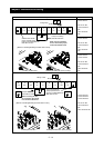
Note:
If the emergency stop function is used, terminals 1 and 3 are used
exclusively for the function. For details, see Item (3), "Emergency stop
function" (on page 2-8).
[Conditions for turning
contact input on]
Voltage across input and
PLC: 18 VDC or more
Input impedance between
input and PLC: 4.7kΩ
Maximum allowable voltage
across input and PLC: 27
VDC
Load current with 27 VDC
power: about 5.6 mA