


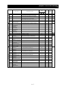
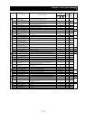
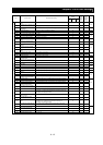
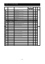
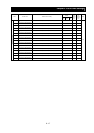
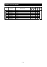

Chapter 8 List of Data Settings
8 - 15
Default
Code Function name Monitored data or setting
_FF _FEF _FUF
Setting
during
operation
(allowed
or not)
Change
during
operation
(allowed
or not)
Page
P001
Operation mode on expansion card
1 error
00 (tripping), 01 (continuing operation) 00
¯ {
P002
Operation mode on expansion card
2 error
00 (tripping), 01 (continuing operation) 00
¯ {
4-79
P011
Encoder pulse-per-revolution
(PPR) setting
128. to 9999., 1000 to 6553(10000 to 65535) (pulses) 1024.
¯ ¯
4-96
P012 Control pulse setting 00 (ASR), 01 (APR), 02 (APR2), 03 (HAPR) 00
¯ ¯
4-96
P013 Pulse train mode setting 00 (mode 0), 01 (mode 1), 02 (mode 2) 00
¯ ¯
4-99
P014 Home search stop position setting 0. to 4095. 0.
¯ {
P015 Home search speed setting "start frequency" to "maximum frequency" (up to 120.0) (Hz) 5.00
¯ {
P016 Home search direction setting 00 (forward), 01 (reverse) 00
¯ ¯
4-104
P017
Home search completion range
setting
0. to 9999., 1000 (10000) (pulses) 5.
¯ {
4-99
P018
Home search completion delay
time setting
0.00 to 9.99 (s) 0.00
¯ {
4-99
P019
Electronic gear set position
selection
00 (feedback side), 01 (commanding side) 00
¯ {
P020
Electronic gear ratio numerator
setting
0. to 9999. 1.
{ {
P021
Electronic gear ratio denominator
setting
0. to 9999. 1.
{ {
4-101
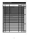
P022 Feed-forward gain setting 0.00 to 99.99, 100.0 to 655.3 0.00
{ {
P023 Position loop gain setting 0.00 to 99.99, 100.0 0.50
{ {
4-101
P024 Position bias setting -204 (-2048.) / -999. to 2048. 0.
{ {
4-103
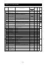
P025
Temperature compensation
thermistor enable
00 (no compensation), 01 (compensation) 00
¯ {
4-87
P026
Over-speed error detection level
setting
0.0 to 150.0 (%) 135.0
¯ {
5-5
P027
Speed deviation error detection
level setting
0.00 to 99.99, 100.0 to120.0 (Hz) 7.50
¯ ¯
4-96
P028 Numerator of motor gear ratio 0. to 9999. 1.
¯ {
P029 Denominator of motor gear ratio 0. to 9999. 1.
¯ {
4-103
P031 Accel/decel time input selection 00 (digital operator), 01 (option 1), 02 (option 2), 03 (easy sequence) 00
¯ ¯
4-10
P032
Positioning command input
selection
00 (digital operator), 01 (option 1), 02 (option 2) 00
¯ {
−
P033 Torque command input selection 00 (O terminal), 01 (OI terminal), 02 (O2 terminal), 03 (digital operator) 00
¯ ¯
P034 Torque command setting 0. to 200. (%) 0.
{ {
P035
Polarity selection at the torque
command input via O2 terminal
00 (as indicated by the sign), 01 (depending on the operation direction) 00
¯ ¯
4-98
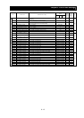
P036 Torque bias mode 00 (disabling the mode), 01 (digital operator), 02 (input via O2 terminal) 00
¯ ¯
P037 Torque bias value -200. to +200. (%) 0.
{ {
P038 Torque bias polarity selection 00 (as indicated by the sign), 01 (depending on the operation direction) 00
¯ ¯
P039
Speed limit for torque-controlled
operation (forward rotation)
0.00 to "maximum frequency" (Hz) 0.00
{ {
P040
Speed limit for torque-controlled
operation (reverse rotation)
0.00 to "maximum frequency" (Hz) 0.00
{ {
4-98
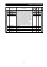
P044 DeviceNet comm watchdog timer 0.00 to 99.99 (s) 1.00
¯ ¯
P045
Inverter action on DeviceNet comm
error
00 (tripping), 01 (tripping after decelerating and stopping the motor), 02
(ignoring errors), 03 (stopping the motor after free-running), 04
(decelerating and stopping the motor)
01
¯ ¯
P046
DeviceNet polled I/O: Output
instance number
20, 21, 100 21
¯ ¯
P047
DeviceNet polled I/O: Input
instance number
70, 71, 101 71
¯ ¯
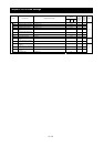
P048
Inverter action on DeviceNet idle
mode
00 (tripping), 01 (tripping after decelerating and stopping the motor), 02
(ignoring errors), 03 (stopping the motor after free-running), 04
(decelerating and stopping the motor)
01
¯ ¯
P049
DeviceNet motor poles setting for
RPM
0, 2, 4, 6, 8, 10, 12, 14, 16, 18, 20, 22, 24, 26, 28, 30, 32, 34, 36, 38
(poles)
0
¯ ¯
−
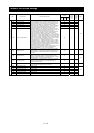
P055 Pulse-string frequency scale 1.0 to 50.0 (kHz) 25.0
¯ {
P056
Time constant of pulse-string
frequency filter
0.01 to 2.00 (s) 0.10
¯ {
P057 Pulse-string frequency bias -100. to +100. (%) 0.
¯ {
Optional functions
P058 Pulse-string frequency limit 0. to 100. (%) 100.
¯ {
4-112