


Chapter 6 Maintenance and Inspection
6 - 3
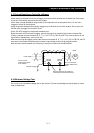
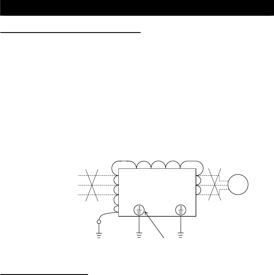
6.3 Ground Resistance Test with a Megger
When testing an external circuit with a megger, disconnect all the external circuit cables from the inverter
to prevent it from being exposed to the test voltage.
Use a tester (in high-resistance range mode) for a conduction test on the control circuit. Do not use a
megger or buzzer for that purpose.
Apply the ground resistance test using a megger only to the main circuit of the inverter. Do not carry out
the test using a megger for its control circuit.
Use a 500 VDC megger for the ground resistance test.
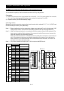
Before the main circuit test with a megger, remove the jumper for switching the inverter's internal filter
function, and then connect terminals R, S, T, U, V, W, P, PD, N, RB, R0, and T0 by wires as shown in the
figure below. Subsequently, carry out the test.
After the test using the megger, remove the wires from terminals R, S, T, U, V, W, P, PD, N, RB, R0, and T0,
and connect the jumper for switching the inverter's internal filter function at the original position.
Note that only inverter models with a capacity of less than 22 kW have the RB terminal.
IM
R
S
T
U
V
W
PP NR
R0
T0
Power suppl
y
Moto
r
Ground
terminal
Ground
terminal
Do not connect
power supply cables
to the inverter.
500 VDC megge
r
Be sure to remove the jumper for
switching the internal filter function.
Do not connect the
inverter cables to the
motor.
6.4 Withstand Voltage Test
Do not carry out a withstand voltage test for the inverter. The test may damage its internal parts or cause
them to deteriorate.