


Chapter 4 Explanation of Functions
4 - 137
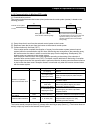
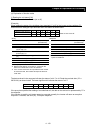
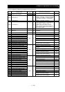
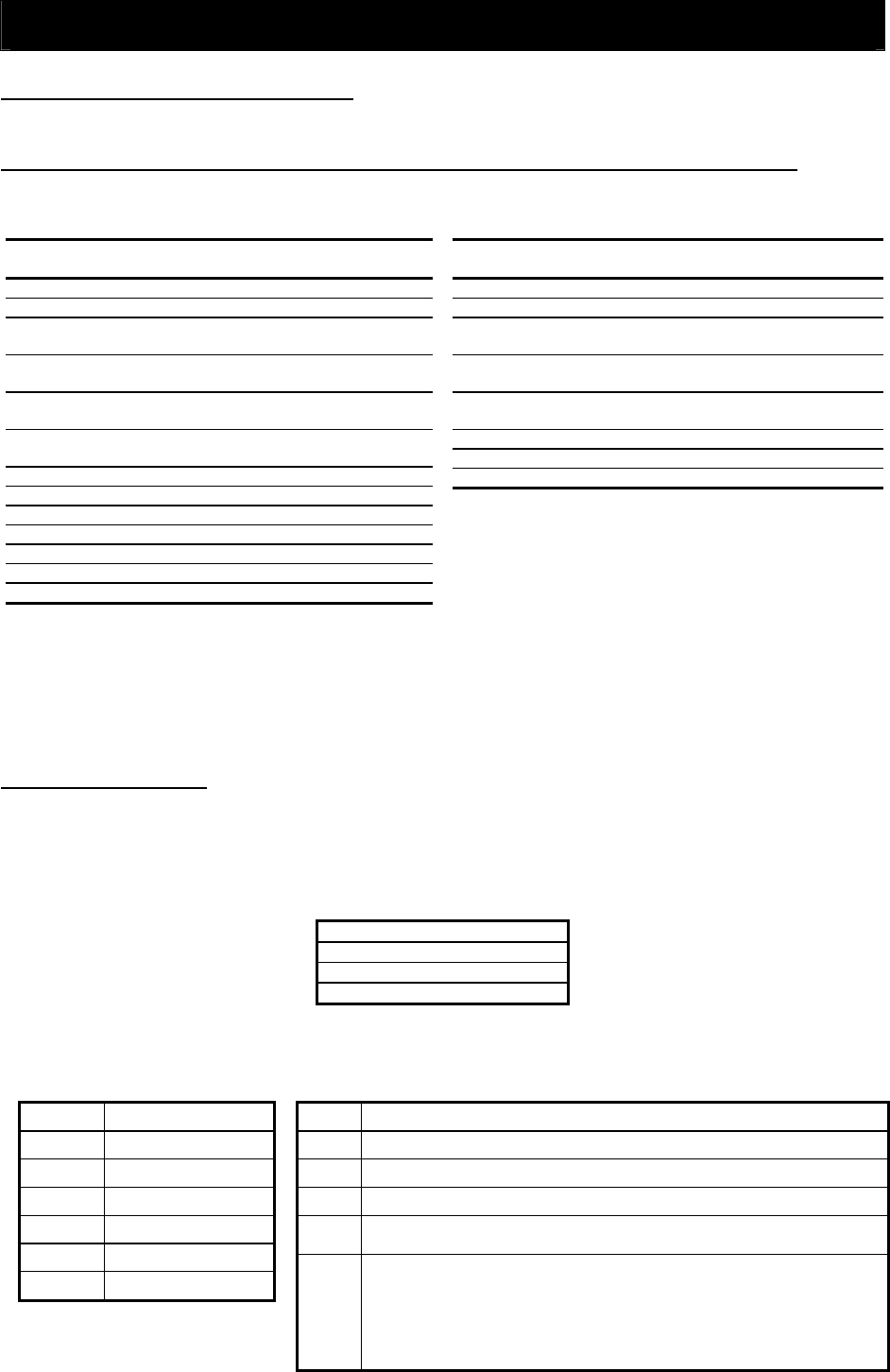
(vii) Writing data to multiple registers [10h]
This function writes data to sequential registers.
(Example)
When setting "3,000 Hz" as the Acceleration (1) time (F002) in the inverter at slave address "1":
Since register "1103h" and "1104h" to store the Acceleration (1) time (F002) have a data resolution of 0.01
seconds, specify "300000" (493E0h) as the updating data to set "3,000 seconds".
If the function to write data to multiple registers cannot be executed normally, the inverter will return an
exception response. For details, see Item (viii), "Exception response."
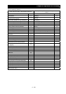
(viii) Exception response
The master system requests the inverter (slave) to return a response upon reception of a query other than
broadcasted queries. The inverter must return the response that matches the query it has received.
However, if an error is found in a query, the inverter will return an exception response.
The exception response consists of the following fields:
Field configuration
Slave address
Function code
Exception code
CRC-16 code
Details of the field configuration are described below. The exception response in reply to a query includes
a function code that is the sum of "80h" and the function code specified by the query. The exception code
in the exception response indicates the content of the error.
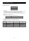
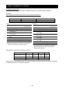
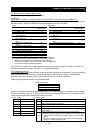
Quer
y
Field name Sample setting
(hexadecimal)
1 Slave address (*1) 01
2 Function code 10
3 Starting register address
(upper digit) (*2)
11
4 Starting register address
(lower digit) (*2)
02
5 Number of registers (upper
digit)
00
6
Number of registers (lower
digit)
02
7 Number of data bytes (*3) 04
8 Updating data 1 (upper digit) 00
9 Updating data 1 (lower digit) 04
10 Updating data 2(upper digit) 93
11 Updating data 2(lower digit) E0
12 CRC-16 code (upper digit) 9E
13 CRC-16 code (lower digit) 9F
*1 If this query is broadcasted, no inverter will return any response.
*2 Note that the starting register address is 1 less than the actual
address of the register to which the data is to be written first.
*3 As the number of bytes, do not specify the number of registers but
the number of bytes to be actually updated.
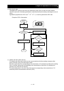
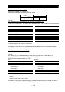
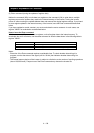
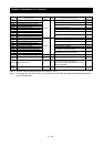
Response
Field name Sample setting
(hexadecimal)
1 Slave address (*1) 01
2 Function code 10
3 Starting register address (upper
digit) (*2)
11
4 Starting register address (lower
digit) (*2)
02
5 Number of registers (upper
digit)
00
6 Number of registers (lower digit) 02
7 CRC-16 code (upper digit) E5
8 CRC-16 code (lower digit) 34
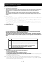
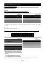
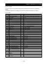
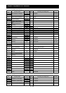
Function codes
Query Exception response
01h 81h
03h 83h
05h 85h
06h 86h
0Fh 8Fh
10h 90h
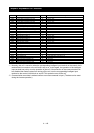
Exception codes
Code Description
01h
An unsupported function is specified.
02h
The specified address is not found.
03h
The specified data has an unacceptable format.
21h
The data to be written to a register exceeds the range of inverter
specifications.
22h
The inverter restricts the execution of the specified function:
- Rewriting a register that cannot be rewritten during the operation
- Issuing an Enter command during the operation (in undervoltage
status)
- Writing to a register during tripping (because of undervoltage)
- Writing to a read-only register (coil)