


Chapter 4 Explanation of Functions
4 - 28
When you specify the 02 RS485 communication for the PV source setting (A076), transfer data as
described below.
1) When the ASCII mode is selected (C078 = 00)
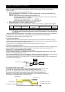
Use the 01 command for data transfer. To transfer feedback data, set the most-significant byte of
frequency data to "1".
Example: When transmitting the frequency data specifying 5 Hz
The data to be transmitted consists of six bytes, indicating a value 100 times as large as
the set frequency value. → "000500"
Change the most-significant byte to "1". → "100500"
Convert the data to ASCII format. → "31 30 30 35 30 30"
Note: In ASCII mode, the unit of setting is always frequency (Hz).
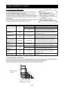
2) When the Modbus RTU mode is selected (C078 = 01)
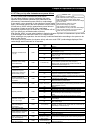
Write the setting data (on the assumption that "10000" indicates 100%) to register address 0006h.
Register
No.
Function name Function code
Readable/writable
(R/W)
Monitored data or setting
Data
resolution
0006h PID feedback - R/W 0 to 10000 0.01 [%]
Note: This register is readable and writable. However, this register can be read only when Modbus
RTU has been specified as the communication mode for PID feedback. It cannot be read with
other settings.
- When pulse train input is specified for PID feedback, the input pulse train frequency (Hz) is converted to a
percentage (with maximum frequency corresponding to 100%) and fetched as the feedback.
For the pulse train input frequency, see Section 4.3.21.
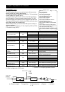
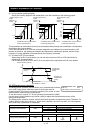
(4) Feed forward selection
- Select the terminal to be used for the feed forward signal through PID feed forward selection (A079).
- Even if the terminal selected for the target or feedback data is also selected for the terminal by A079, the
terminal functions according to the setting of A079.
- Specifying the value to disable selection for A079 disables feed forward control.
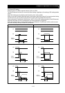
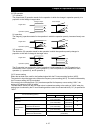
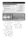
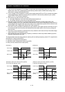
(5) Output of inverted PID deviation
Some sensor characteristics may cause the polarity of the deviation of feedback data from the target value
to be inconsistent with the inverter operation command. If the inconsistency occurs, specify "01" for
function "A077" to invert the polarity of the deviation.
Example: When controlling the compressor for a refrigerator
Assume that the temperature and voltage specifications of the temperature sensor are -20°C to +100°C
and 0 to 10 V and the target value is 0°C.
If the current temperature is 10°C and the inverter is under the normal type of PID control, the inverter will
reduces the output frequency because the feedback data is larger than the target value.
→ In such a case, specify "01" for function "A077" to invert the feedback deviation. Then, the inverter will
increase the output frequency.
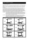
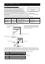
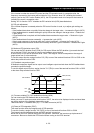
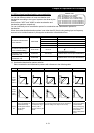
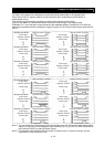
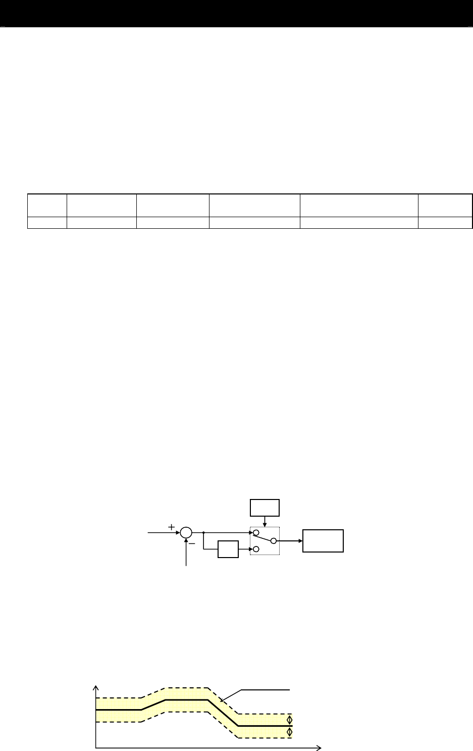
(6) Limitation on PID variation range
You can limit the PID output to within a specific range with reference to the target value.
To use the PID variation limit function, set the PID variation range (A078).
(Set a value on the assumption that the maximum frequency corresponds to 100%.)
The variation of PID output is limited within ±"value of A078" from the target value.
(Setting "0.0" for the PID variation range [A078] disables the PID variation limit function.)
This function is deactivated when 0.0 is set on A078.
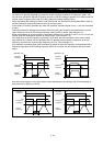
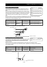
(7) Output of inverted PID deviation
PID
operation
-1
A
077
PID target value
PID feedback data
PID output (%)
PID target value
PID output range
PID variation range (A078)
PID variation range (A078)
Time (s)