Chapter 4 Explanation of Functions
4 - 131
(iv) Error check code
The Modbus-RTU protocol uses the cyclic redundancy check (CRC) as the error check method.
The CRC code is the 16-bit data generated for a data block that has an arbitrary data length (in units of
8 bits).
A generative polynomial for CRC-16 (X
16
+ X
15
+ X
2
+ 1) is used to generate the CRC code.
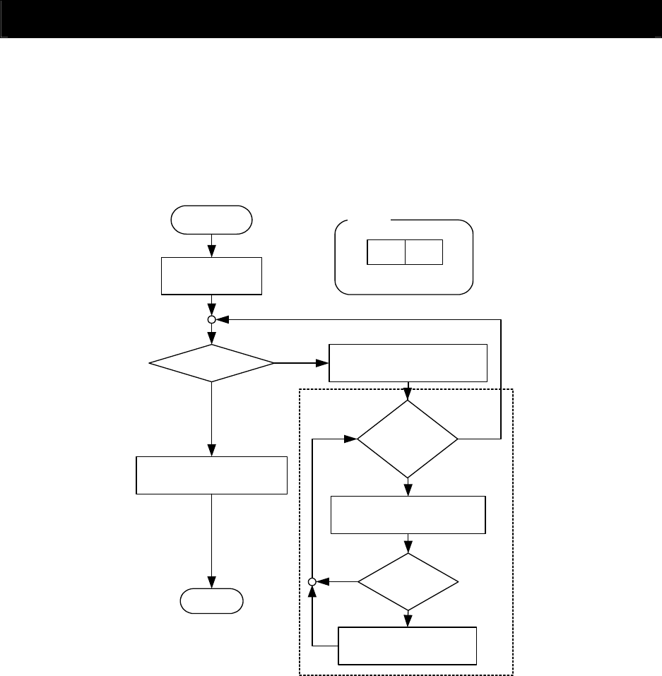
Example of CRC-16 calculation
CRC
*1
= FFFFh
CRC-16
operation
Is the target
data found?
Set the XOR of CRC*1 data and
target data in CRC*1
Does any
bit remain after 8-bit
shifting?
Shift CRC*1 to the left by 1 bit
Is the
bit put out of
CRC*1 "1"?
Replace the Hi and Lo bytes
of CRC*1 with each other
End
Set the XOR of CRC*1 data
and A001h in CRC*1
Yes
No
No
Yes
Yes
No
Hi Lo
CRC register (2 bytes)
CRC
*1
The target data is shifted by 1 byte.
(v) Header and trailer (silent interval)
The header and trailer set the total time the inverter should wait before sending a response after
having received a query from the master system.
Be sure to specify the time corresponding to the transmission of 3.5 characters (24 bits) as the waiting
time. If a shorter waiting time (corresponding to the transmission of fewer than 3.5 characters) is
specified, the inverter will not respond.
The actual waiting time is the sum of the silent interval (corresponding to the transmission of 3.5
characters) and the communication wait time (C078).


