


Chapter 4 Explanation of Functions
4 - 86
c) All brakes are released.
d) During auto-tuning, insufficient torque may cause a problem in the load driven by the motor (for
example, a lift may slide down). Therefore, remove the motor from the machine or other load, and
perform auto-tuning with the motor alone. (The moment of inertia [J] measured by auto-tuning is that of
the motor alone. To apply the data, add the moment of inertia of the load machine to the measured J
data after converting the moment of inertia into the motor shaft data.)
e) If the motor is installed in a machine (e.g., lift or boring machine) that limits the motor shaft rotation, the
allowable rotation limit may be exceeded during auto-tuning, and the machine may be damaged. To
avoid this problem, specify "01" (auto-tuning without motor rotation) for the Auto-tuning Setting (H001).
f) If the no-load current is unknown, operate the motor at 50 Hz in a V/f characteristic control mode to
measure the motor current with current monitor. Then, set the measured current as the control
constant "H023" or "H223" before auto-tuning.
5) Even when "01" (auto-tuning without motor rotation) is specified for the Auto-tuning Setting (H001), the
motor may rotate slightly during auto-tuning.
6) When performing the auto-tuning for a motor of which the capacity is one class lower than that of the
inverter, enable the overload restriction function, and set the overload restriction level to 1.5 times as
high as the rated current of the motor.
Operating procedure
1) Specify "01" or "02" for the Auto-tuning Setting (H001).
2) Input an operation command.
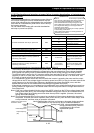
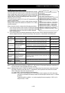
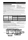
When the operation command is input, the inverter performs an automatic operation in the following steps:
(1) First AC excitation (The motor does not rotate.)
↓
(2) Second AC excitation (The motor does not rotate.)
↓
(3) First DC excitation (The motor does not rotate.)
↓
(4) Operation based on V/f characteristic control (The motor rotates at a
speed up to 80% of the base frequency.)
↓
(5) Operation based on SLV control (The motor rotates at a speed up to
x% of the base frequency.)
↓
(6) Second DC excitation (The motor does not rotate.)
↓
(7) Display of auto-tuning result
Note 1: Steps (4) and (5) are skipped when the auto-tuning without motor rotation (H001 = 01) has been
selected.
Note 2: The motor speed (x) in step (5) is as follows. Assume that "T" is the acceleration or deceleration
time in step (4), whichever is largest.
When 0s ≤ T < 50 s, x = 40%.
When 50 s ≤ T < 100 s, x = 20%.
When 100 s ≤ T, x = 10%.
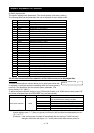
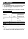
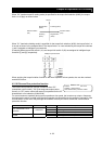
Note 3: The tuning result is displayed as follows:
If the auto-tuning has ended abnormally, retry it.
(To clear the result display, press the STOP/RESET key.)
Note 4: If the inverter trips during the auto-tuning, the auto-tuning is terminated forcibly.
(In such cases, the monitor does not display the abnormal-end code, but displays a trip indication
code.)
In such cases, remove the cause of tripping, and then set H001=01 again to retry the auto-tuning.
Note 5: If you cancel the auto-tuning midway with a stop command (by pressing the STOP/RESET key or
turning off the operation command), the constants set for auto-tuning may remain in the inverter.
Before retrying the auto-tuning, initialize the inverter, and then readjust the settings for the
auto-tuning. (Perform the same procedure also when you proceed to the normal inverter
operation.)
Note 6: If an attempt is made to perform the auto-tuning with a free V/f characteristic selected as the
control mode, the inverter will soon terminate the operation with the abnormal-end code displayed.
Note 7: Even if the auto-tuning has ended normally, you cannot operate the inverter with the tuning data
left. If you intend to operate the inverter with the tuning data left, be sure to switch the setting of
motor constant selection (H002) to "01".
Normal end
Abnormal end