


Appendix
A - 1
Upgrading from the SJ300 Series
The SJ300 series inverter is upwardly compatible with the SJ700 series inverter. Therefore, you can:
- mount the control circuit terminal block board of the SJ300 series in the SJ700 series without removing
the connected cables,
- copy the parameter settings from the SJ300 series into the SJ700 series, and
- use the option boards mounted in the SJ300 series for the SJ700 series without removing the connected
cables.
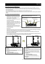
(1) Control circuit terminal block board
Control circuit terminal block board mounted in the
SJ300/SJ700 series (front view)
Fixing screw (M3) x 2
Fixing screw
Board guide pin Board guide pin
Fixing screw
Connector
(60 poles)
Board guide pin x 2
Precautions:
Use care to prevent the control circuit terminal block board from twisting when removing or mounting it.
Otherwise, the board guide pins and connector pins may be damaged.
Do not pull the cables connected to the control circuit terminal block board when you remove the
board from the SJ300 series.
Do not forcibly insert the board into the mounting slot. Make sure that the board is correctly fitted onto
the board guide pins and the connectors are correctly fitted to each other.
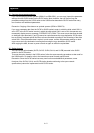
Removing the control circuit terminal block board from the
SJ300 series
1) Remove two fixing screws from the control circuit terminal
block board.
2) Pull the control circuit terminal block board straight toward
you to remove it from the SJ300 series.
Precautions:
Pull out the board slowly.
Be careful not to bend the connector pins.
Be careful not to break the board guide pins.
Mounting the removed control circuit terminal block board in
the SJ700 series
3) Remove the original control circuit terminal block board
from the SJ700 series beforehand (as instructed in steps
1) and 2)).
4) Insert the control circuit terminal block board removed
from the SJ300 series straight into the slot along the
board guide pins and connector pins until it touches the
fixing-screw seats.
Precautions:
Push in the board slowly.
Be careful not to bend the connector pins.
Be careful not to break the board guide pins.
5) Secure the control circuit terminal block board with two
fixing screws.
Precaution:
Be sure to fix the board with the two fixing screws.
You can mount the control circuit terminal
block board of the SJ300 series into the
SJ700 series. Note, however, that the
backing plate is incompatible.
(Procedure for replacing the control circuit
terminal block board)
As shown in the figure on the right, the
fixing screw locations on the control circuit
terminal block board are common to the
SJ300 and SJ700 series.
To remove and install the control circuit
terminal block board, follow the steps 1) to
5) described below.
SJ300 series SJ700 series