


Chapter 2 Installation and Wiring
2 - 9
About the emergency stop function
(disabled by the factory setting)
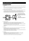
- The emergency stop function shuts off the inverter output (i.e. stops the switching operation of the main
circuit elements) in response to a command from a hardware circuit via an intelligent input terminal
without the operation by internal CPU software.
Note: The emergency stop function does not electrically shut off the inverter but merely stops the switching
operation of the main circuit elements. Therefore, do not touch any terminals of the inverter or any
power lines, e.g., motor cables. Otherwise, electric shock, injury, or ground fault may result.
- When the emergency stop function is enabled, intelligent input terminals 1 and 3 are used exclusively for
this function, and no other functions can be assigned to these terminals. Even if other functions have
been assigned to these terminals, these are automatically disabled and these terminals are used
exclusively for the emergency stop function.
Terminal [1] function:
This terminal always serves as the a (NO) contact for the reset (RS) signal.
This signal resets the inverter and releases the inverter from the trip due to emergency stop (E37.*).
Terminal [3] function:
This terminal always serves as the b (NC) contact for the emergency stop (EMR) signal.
This signal shuts off the inverter output without the operation by internal CPU software.
This signal makes the inverter trip due to emergency stop (E37.*).
Note: If intelligent input terminal 3 is left unconnected, the cable connected to the terminal is disconnected,
or the signal logic is improper, the inverter trips due to emergency stop (E37.*). If this occurs, check
and correct the wiring and signal logic, and then input the reset (RS) signal.
Only the reset (RS) signal input from intelligent input terminal [1] can release the inverter from
tripping due to emergency stop (E37.*). (The inverter cannot be released from the E37.* status by
any operation from the digital operator.)
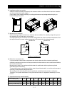
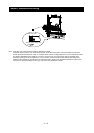
- To enable the emergency stop function, set the slide lever of slide switch SW1 to ON. (With the factory
setting, slide switch SW1 is set to OFF to disable the function.)
Note: Before operating slide switch SW1, make sure that the input power supply is off.
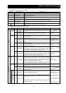
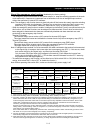
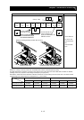
Setting of slide switch SW1 setting and function selection for intelligent input terminals [1] and [3]
Intelligent input terminal [1] Intelligent input terminal [3]
Setting of slide switch
SW1
Terminal [1] function [C001]
a/b (NO/NC) selection
[C011] (*1)
Terminal [3] function [C003]
a/b (NO/NC) selection
[C013] (*1) (*2)
Selectable arbitrarily (*4) Selectable arbitrarily (*4) Selectable arbitrarily (*4) Selectable arbitrarily (*4) SW1 is OFF.
Emergency stop
disabled
(factory setting)
Factory
setting
18 (RS)
Factory
setting
00 (NO)
Factory
setting
06 (JG)
Factory
setting
00 (NO)
Automatic assignment of functions to intelligent input terminals [1] and [3] and the terminal to which function "18 (RS)" has been
assigned (*3)
SW1 is ON.
Emergency stop
enabled (*5)
Fixed function
(cannot be
changed)
18 (RS)
Fixed function
(cannot be
changed)
00 (NO)
Fixed function
(cannot be
changed)
64 (EMR)
Fixed function
(cannot be
changed)
01 (NC)
Selectable arbitrarily (*4) Selectable arbitrarily (*4) Selectable arbitrarily (*4) Selectable arbitrarily (*4)
SW1 is ON (after
setting to OFF once).
Emergency stop
disabled (*3) (*5)
Setting made
when SW1 is
set ON
retained
18 (RS)
Setting made
when SW1 is
set ON
retained
00 (NO)
Released
from
emergency
stop function
no
(No function
assigned)
Setting made
when SW1 is
set ON
retained
01 (NC)
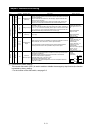
*1 When function "18 (RS)" is assigned to the input terminal, "a/b (NO/NC)" selection is always "00 (NO)".
*2 When terminal setting "C003" is "64 (EMR)", terminal setting "C013" is always "01 (NC)".
*3 If function "18 (RS)" has been assigned to an intelligent input terminal other than intelligent input terminals [1] and [3]
before slide switch SW1 is set to ON, the input terminal setting for said terminal is automatically changed to "no (no
function assigned)" when slide switch SW1 is set to ON to prevent any duplication of terminal functions. Even if slide
switch SW1 is subsequently returned to OFF, the original function setting for said terminal will not be restored. If
necessary, the original function will have to be re-assigned to said terminal.
Example: If slide switch SW1 is set to ON when function "18 (RS)" has been assigned to input terminal 2 (by terminal
setting "C002"), terminal setting "C002" is changed to "no (no function assigned)," and function "18 (RS)" is assigned to
input terminal 1 (by terminal setting "C001").
Even if slide switch SW1 is subsequently returned to OFF, terminal [2] function "C002" and terminal [1] function "C001"
will remain as "no (no function assigned)" and "18 (RS)," respectively.
*4 Function "64 (EMR)" cannot be assigned to input terminal 3 by an operation from the digital operator. The function is
automatically assigned to the terminal when slide switch SW1 is set to ON.
*5 After slide switch SW1 has been set to ON once, function assignments to intelligent input terminals [1] and [3] are not
returned to their original assignments. If necessary, re-assign original functions to the intelligent input terminals.