


Chapter 4 Explanation of Functions
4 - 6
4.1.27 Trip monitoring 1 to 6
When the trip monitoring function (d081 to d086) is selected, the inverter
displays the trip history data. The last six protective trips the inverter
made can be displayed.
Select the trip monitoring 1 (d081) to display the data on the most recent
trip.
(Display contents)
1) Factor of tripping (one of E01 to E79) (*1)
2) Output frequency at tripping (Hz)
3) Output current at tripping (A) (*2)
4) Main circuit DC voltage at tripping (V) (*3)
5) Cumulative inverter-running time until tripping (h)
6) Cumulative inverter power-on time until tripping (h)
*1 See Section 5.1.1, "Protective functions."
*2 When the inverter status is in stop mode as a trip history, monitored value can be zero.
*3 When grounding fault is detected at power on, monitored value can be zero.
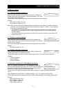
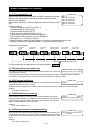
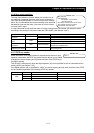
(Display by trip monitoring)
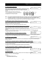
*2 If the inverter has not tripped before, the inverter displays .
4.1.28 Programming error monitoring
If an attempt is made to set the data conflicting with other data on the inverter, the
inverter displays a warning.
The PRG (program) lamp lights up while the warning is displayed (until the data is rewritten forcibly or corrected).
For details on the programming error monitoring function, see Section 5.2. Warning Codes
4.1.29 DC voltage monitoring
When the DC voltage monitoring is selected, the inverter displays the DC voltage
(across terminals P and N) of the inverter.
While the inverter is operating, the monitored value changes as the actual DC voltage of the inverter changes.
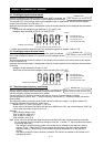
(Display)
0.0 to 999.9 in steps of 0.1 V
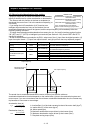
4.1.30 BRD load factor monitoring
When the BRD load factor monitoring function (d103) is selected, the inverter
displays the BRD load factor. If the BRD load factor exceeds the value set as the
dynamic braking usage ratio (b090), the inverter will trip because of the braking
resistor overload protection (error code "E06").
(Display)
0.0 to 100.0 in steps of 0.1%
4.1.31 Electronic thermal overload monitoring
When the electronic thermal overload monitoring function (d104) is selected, the
inverter displays the electronic thermal overload. If the electronic thermal overload
exceeds 100%, the inverter will trip because of the overload protection (error code
"E05").
(Display)
0.0 to 100.0 in steps of 0.1%
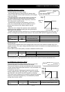
d081: Trip monitoring 1
d082: Trip monitoring 2
d083: Trip monitoring 3
d084: Trip monitoring 4
d085: Trip monitoring 5
d086: Trip monitoring 6
Related code
1) Factor of
tripping
(*2)
2) Frequency
at tripping
3) Current at
tripping
4) Main circuit DC
voltage at tripping
5) Cumulative
running time
6) Cumulative
power-on time
FUNC
FUNC
d090: Programming error monitoring
Related code
d102: DC voltage monitoring
Related code
d103: BRD load factor monitoring
b090: Dynamic braking usage ratio
Related code
d104: Electronic thermal overload
monitoring
Related code