


Chapter 2 Installation and Wiring
2 - 6
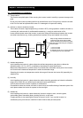
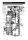
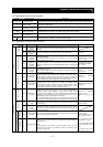
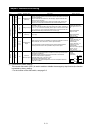
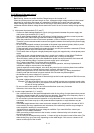
2.2.1 Terminal connection diagram and explanation of terminals and switch settings
3
-
phase power supply
200 V class: 200 to 240 V +10%, -
15%
(50/60 Hz ±5%)
400 V class: 380 to 480 V +10%, -
15%
(50/60 Hz ±5%)
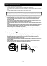
Jumper
When connecting separate
power supplies to main and
control circuits, remove J51
connector cables beforehand.
(See page 2-20)
Power supply for
control circuit
Forward rotation
command
Intelligent input
(8 contacts)
Digital monitor output
(PWM output)
Thermistor
Frequency
setting circuit
500 to 2,000Ω
0 to 10 VDC (12 bits)
-
1
0 to
+
10 VDC (12 bits)
4 to 20 mA (12 bits)
Analog monitor
output (voltage
output)
Analog monitor
output (current
output)
0 to 10 V (10 bits)
4 to 20
mA (10 bits)
Motor
Jumper
bar
Braking resistor
(optional)
(Models with 22 kW
or less capacity
have a built-
in BRD
circuit.)
The dotted line indicates the
detachable control terminal
board.
Intelligent relay output contact
(default: alarm output)
Intelligent output
(5 terminals)
For terminating
resistor
Option 1
Option 2
Type
-
D grounding (for 200 V class model)
Type-C grounding (for 400 V class model)
(See page 2-11.)
PLC
PLCPLC
PLC
P24
P24P24
P24
DC24V
DC24VDC24V
DC24V
CM1
CM1CM1
CM1
R
RR
R
S
SS
S
T
TT
T
R0
R0R0
R0
T0
T0T0
T0
U
UU
U
V
VV
V
W
WW
W
P
PP
P
PD
PDPD
PD
RB
RBRB
RB
N
NN
N
FW
FWFW
FW
7
77
7
6
66
6
1
11
1
8
88
8
FM
FMFM
FM
CM
CMCM
CM1
11
1
H
HH
H
O
OO
O
O2
O2O2
O2
OI
OIOI
OI
L
LL
L
AM
AMAM
AM
AMI
AMIAMI
AMI
SP
SPSP
SP
SN
SNSN
SN
RP
RPRP
RP
SN
SNSN
SN
RS485
RS485RS485
RS485
AL0
AL0AL0
AL0
AL1
AL1AL1
AL1
AL2
AL2AL2
AL2
1
11
1
2
22
2
HITACHI
POWER
ALARM
Hz
V
A
%
kW
RUN
PRG
運転
RUN
機能
FUNC
記憶
STR
停止
/
リセット
DC10V
DC10VDC10V
DC10V
100Ω
10kΩ
10kΩ
15
1515
15
11
1111
11
CM2
CM2CM2
CM2
R
RR
R
T
TT
T
TH
THTH
TH
J51
J51J51
J51
STOP/RESET
IM
IMIM
IM
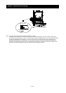
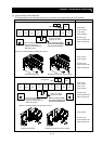
Default jumper position
for-xFUF2/xFF2 models
(sinking type inputs)
Default jumper position
for-xFEF2 models
(sourcing type inputs)