


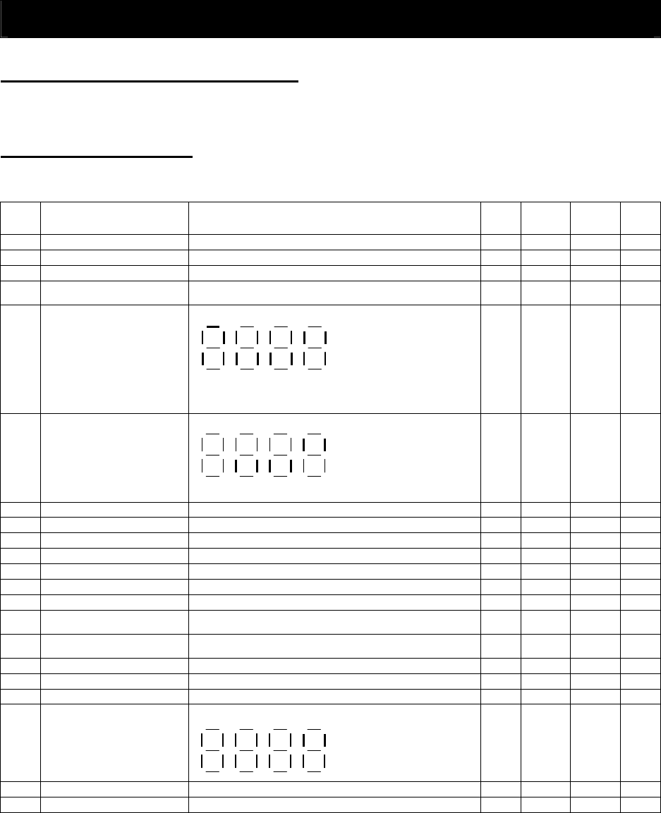
Chapter 8 List of Data Settings
8 - 1
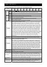
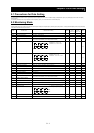
8.1 Precautions for Data Setting
The default display mode limits the screens (parameters) that can be displayed on the monitor. To enable the display of all parameters, specify "00" (full display) for the function code display
restriction (b037).
To enable the parameters to be changed while the inverter is operating, specify "10" for the software lock mode selection (b031).
8.2 Monitoring Mode
With the default settings, the monitor always displays the data output according to the output frequency monitoring (d001) after power-on. To change the initial display content, change the setting
of the initial-screen selection (b038) as required.
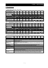
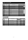
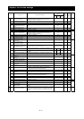
Code Function name Monitored data or setting Default
Setting during
operation
(allowed or not)
Change during
operation
(allowed or not)
Page
d001 Output frequency monitoring 0.00 to 99.99, 100.0 to 400.0 (Hz)
−
{
−
4-1
d002 Output current monitoring 0.0 to 999.9, 1000 to 9999 (A)
− − −
4-1
d003 Rotation direction minitoring F (forward rotation), o (stopped), r (reverse rotation)
− − −
4-1
d004 Process variable (PV), PID feedback
monitoring
0.00 to 99.99, 100.0 to 999.9, 1000. to 9999.
1000 to 9999 (10000 to 99990), ⎡100 to ⎡999 (100000 to 999000)
− − −
4-1
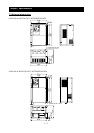
d005 Intelligent input terminal status (Example)
Terminals FW, 7, 2, and 1: ON
Terminals 8, 6, 5, 4, and 3: OFF
− − −
4-2
d006 Intelligent output terminal status (Example)
Terminals 12 and 11: ON
Terminals AL, 15, 14, and 13: OFF
− − −
4-2
d007 Scaled output frequency monitoring 0.00 to 99.99, 100.0 to 999.9, 1000. to 9999., 1000 to 3996 (10000 to 39960)
−
{
−
4-2
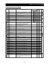
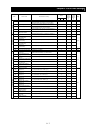
d008 Actual-frequency monitoring -400. to -100., -99.9 to 0.00 to 99.99, 100.0 to 400.0 (Hz)
− − −
4-3
d009 Torque command monitoring -200. to +200. (%)
− − −
4-3
d010 Torque bias monitoring -200. to +200. (%)
− − −
4-3
d012 Torque monitoring -200. to +200. (%)
− − −
4-3
d013 Output voltage monitoring 0.0 to 600.0 (V)
− − −
4-3
d014 Power monitoring 0.0 to 999.9 (kW)
− − −
4-3
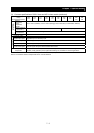
d015 Cumulative power monitoring 0.0 to 999.9, 1000. to 9999.
1000 to 9999 (10000 to 99990), ⎡100 to ⎡999 (100000 to 999000)
− − −
4-4
d016 Cumulative operation RUN time
monitoring
0. to 9999., 1000 to 9999 (10000 to 99990), ⎡100 to ⎡999 (100000 to 999000) (hr)
− − −
4-4
d017 Cumulative power-on time monitoring
0. to 9999., 1000 to 9999 (10000 to 99990), ⎡100 to ⎡999 (100000 to 999000) (hr) − − −
4-4
d018 Heat sink temperature monitoring
-020. to 200.0 (°C) − − −
4-4
d019 Motor temperature monitoring
-020. to 200.0 (°C) − − −
4-4
d022 Life-check monitoring 1: Capacitor on main circuit board
2: Cooling-fan speed drop
− − −
4-5
d023 Program counter 0 to 512
− − −
4-5
d024 Program number monitoring 0000 to 9999
− − −
4-5
FW
8 7
6
5
4
3 2 1
AL 15 14 13 12 11
2 1
ON
OFF