


Chapter 2 Installation and Wiring
2 - 8
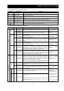
Symbol
Terminal name
Description Electric property
Contact input
Function selection
and logic switching
PLC
Intelligent input
(common)
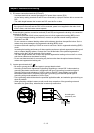
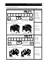
To switch the control logic between sink logic and source logic, change the
jumper connection of this (PLC) terminal to another terminal on the control
circuit terminal block.
Jumper terminals P24 and PLC for the sink logic; jumper terminals CM1
and PLC for the sink logic.
To use an external power supply to drive the contact inputs, remove the
jumper, and connect the PLC terminal to the external interface circuit.
11
12
13
14
15
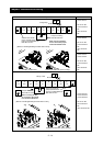
Intelligent output
Select five of a total 51 functions, and assign these five functions to
terminals 11 to 15.
If you have selected an alarm code using the function "C062", terminals 11
to 13 or 11 to 14 are used exclusively for the output of cause code for alarm
(e.g., inverter trip). The control logic between each of these terminals and
the CM2 terminal always follows the sink or source logic.
Open collector output
Status and factor
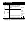
CM2
Intelligent output
(common)
This terminal serves as the common terminal for intelligent output terminals
[11] to [15].
Voltage drop between each
terminal and CM2 when
output signal is on: 4 V or
less
Maximum allowable
voltage: 27 VDC
Maximum allowable
current: 50 mA
Digital (contact)
Relay contact output
Status and alarm
AL0
AL1
AL2
Intelligent relay
output
Select functions from the 43 available, and assign the selected functions to
these terminals, which serve as C contact output terminals.
In the initial setting, these terminals output an alarm indicating that the
inverter protection function has operated to stop inverter output.
(Maximum contact
capacity)
AL1-AL0: 250 VAC, 2 A
(resistance) or 0.2 A
(inductive load)
AL2-AL0: 250 VAC, 1 A
(resistance) or 0.2 A
(inductive load)
(Minimum contact capacity)
100 VAC, 10 mA
5 VDC, 100 mA
Analog
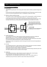
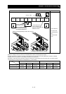
Analog input
Sensor
TH
External
thermistor input
Connect to an external thermistor to make the inverter trip if an abnormal
temperature is detected.
The CM1 terminal serves as the common terminal for this terminal.
[Recommended thermistor properties]
Allowable rated power: 100 mW or more
Impedance at temperature error: 3kΩ
The impedance to detect temperature errors can be adjusted within the
range 0Ω to 9,999Ω.
Allowable range of input
voltages
0 to 8 VDC
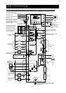
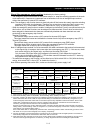
[Input circuit]
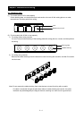
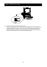
(3) Explanation of switch settings
The internal slide switch (SW1) is used to enable or disable the emergency stop function (the function
is disabled by factory setting).
* For the location of the slide switch, see page 2-9.
DC8V
10kΩ
1kΩ
CM1
TH
Thermistor