


Chapter 7 Specifications
7 - 2
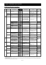
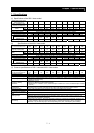
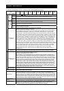
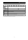
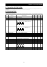
(3) Common specifications of 200 V class and 400 V class models (continued)
Model name (type
name)
SJ700-XXXXXFF.FEFFUF
055
L/H
075
L/H
110
L/H
150
L/H
185
L/H
220
L/H
300
L/H
370
L/H
450
L/H
550
L/H
Standard
operator
Setting with
1
and
2
keys
External
signal
0 to +10 VDC, -10 to +10 VDC (input impedance: 10kΩ), 4 to 20 mA (input impedance: 100Ω)
Fre-
quency setting
External
port
Setting via RS485 communication
Standard
operator
Start/stop commands (forward/reverse switching by parameter setting)
External
signal
Forward-operation start/stop commands (reverse-operation start/stop possible when relevant commands
are assigned to intelligent input terminals)
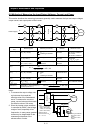
3-wire input possible (when relevant commands are assigned to control circuit terminals)
Start/stop
command
Forward/reverse
command
External
port
Setting via RS485 communication
Intelligent input
terminals
8 terminals, NO/NC switchable, sink logic/source logic switchable
[Terminal functions] Select eight of 69 functions.
Reverse operation (RV), Multispeed 1 setting (CF1), Multispeed 2 setting (CF2), Multispeed 3 setting
(CF3), Multispeed 4 setting (CF4), Jogging (JG), external DC braking (DB), 2nd motor control (SET),
2-stage acceleration/deceleration (2CH), free-run stop (FRS), external trip (EXT), unattended start
protection (USP), commercial power supply switching (CS), software lock (SFT), analog input switching
(AT), 3rd motor control (SET3), reset (RS), starting by 3-wire input (STA), stopping by 3-wire input (STP),
forward/reverse switching by 3-wire input (F/R), PID disable (PID), PID integration reset (PIDC), control
gain switching (CAS), acceleration by remote control (UP), deceleration by remote control (DWN), data
clearance by remote control (UDC), forcible operation (OPE), multispeed bit 1 (SF1), multispeed bit 2
(SF2), multispeed bit 3 (SF3), multispeed bit 4 (SF4), multispeed bit 5 (SF5), multispeed bit 6 (SF6),
multispeed bit 7 (SF7), overload restriction selection (OLR), torque limit selection (enabling/disabling)
(TL), torque limit 1 (TRQ1), torque limit 2 (TRQ2), P/PI switching (PPI), braking confirmation (BOK),
orientation (ORT), LAD cancellation (LAC), clearance of position deviation (PCLR), permission of 90°-shift
phase (STAT), trigger for frequency addition (A145) (ADD), forcible-terminal operation (F-TM), permission
of torque command input (ATR), cumulative power clearance (KHC), servo-on (SON), pre-excitation
(FOC), general-purpose input 1 (MI1), general-purpose input 2 (MI2), general-purpose input 3 (MI3),
general-purpose input 4 (MI4), general-purpose input 5 (MI5), general-purpose input 6 (MI6),
general-purpose input 7 (MI7), general-purpose input 8 (MI8), analog command holding (AHD), no
assignment (no)
Input
Thermistor input
terminal
1 terminal (positive temperature coefficient/negative temperature coefficient switchable for resistor)
Intelligent output
terminals
5 open-collector output terminals, NO/NC switchable, sink logic/source logic switchable
1 relay (1c-contact) output terminal: NO/NC switchable
[Terminal functions] Select six of 51 functions.
Running (RUN), constant-speed reached (FA1), set frequency overreached (FA2), overload notice
advance signal (1) (OL), output deviation for PID control (OD), alarm signal (AL), set frequency reached
(FA3), over-torque (OTQ), instantaneous power failure (IP), undervoltage (UV), torque limited (TRQ),
operation time over (RNT), plug-in time over (ONT), thermal alarm signal (THM), brake release (BRK),
braking error (BER), 0 Hz detection signal (ZS), speed deviation maximum (DSE), positioning completed
(POK), set frequency overreached 2 (FA4), set frequency reached 2 (FA5), overload notice advance
signal (2) (OL2), PID feedback comparison (FBV), communication line disconnection (NDc), logical
operation result 1 (LOG1), logical operation result 2 (LOG2), logical operation result 3 (LOG3), logical
operation result 4 (LOG4), logical operation result 5 (LOG5), logical operation result 6 (LOG6), capacitor
life warning (WAC), cooling-fan speed drop (WAF), starting contact signal (FR), heat sink overheat
warning (OHF), low-current indication signal (LOC), general-purpose output 1 (M01), general-purpose
output 2 (M02), general-purpose output 3 (M03), general-purpose output 4 (M04), general-purpose
output 5 (M05), general-purpose output 6 (M06), inverter ready (IRDY), forward rotation (FWR), reverse
rotation (RVR), major failure (MJA), alarm code 0 to 3 (AC0 to AC3)
Output
Intelligent monitor
output terminals
Analog voltage output, analog current output, pulse-string output (e.g., A-F, D-F [n-fold, pulse output only],
A, T, V, P)
Monitoring on display
Output frequency, output current, output torque, frequency conversion data, trip history, input/output
terminal status, electric power, and others
Other functions
Free V/f setting (7 breakpoints), frequency upper/lower limit, jump (center) frequency,
acceleration/deceleration according to characteristic curve, manual torque boost level/breakpoint,
energy-saving operation, analog meter adjustment, start frequency setting, carrier frequency adjustment,
electronic thermal function (available also for free setting), external start/end frequency/frequency rate,
analog input selection, retry after trip, restart after instantaneous power failure, output of various signals,
starting with reduced voltage, overload restriction, initial-value setting, automatic deceleration at power
failure, AVR function, fuzzy acceleration/deceleration, online/offline auto-tuning, high-torque multi-motor
operation (sensorless vector control of two motors by one inverter)
Carrier frequency
variation
0.5 to 15 kHz
Protective functions
Overcurrent protection, overvoltage protection, undervoltage protection, electronic thermal protection,
temperature error protection, instantaneous power failure protection,
phase loss input protection,
braking-resistor overload protection, ground-fault current detection at power-on, USP error, external trip,
emergency stop trip, CT error, communication error, option board error, and others