


Chapter 3 Operation
3 - 2
You can operate the inverter in different ways, depending on how to input the operation and
frequency-setting commands as described below.
This section describes the features of operating methods and the items required for operation.
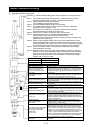
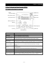
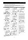
(1) Entering operation and frequency-setting commands from the digital operator
This operating method allows you to operate the inverter through key operations on the standard
digital operator mounted in the inverter or an optional digital operator.
When operating the inverter with a digital operator alone, you need not wire the control circuit
terminals.
(Items required for operation)
1) Optional digital operator (not required when you use the standard digital operator)
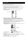
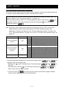
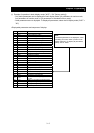
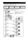
(2) Entering operation and frequency-setting commands via control circuit terminals
This operating method allows you to operate the inverter via the input of operation signals from
external devices (e.g., frequency-setting circuit and start switch) to control circuit terminals.
The inverter starts operation when the input power supply is turned on and then an operation
command signal (FW or RV) is turned on.
You can select the frequency-setting method (setting by voltage specification or current specification)
through the input to a control circuit terminal according to your system. For details, see Item (2),
"Explanation of control circuit terminals," in Section 2.2.1 (on pages 2-7 and 2-8).
(Items required for operation)
1) Operation command input device: External switch or relay
2) Frequency-setting command input device: External device to input signals (0 to 10 VDC, -10 to +10
VDC, or 4 to 20 mA)
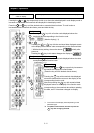
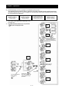
(3) Entering operation and frequency-setting commands; both from a digital operator and via control
circuit terminals
This operating method allows you to arbitrarily select the digital operator or control circuit terminals as
the means to input operation commands and frequency-setting commands.
(Items required for operation)
1) See the items required for the above two operating methods.
Digital operato
r
Operation command input
device (switch)
Frequency-setting command
input device (control)
Control circuit
terminal block
H
O
L
CM1(for -xFF/xFUF),
P24(for –xFEF)
FW