


Chapter 4 Explanation of Functions
4 - 26
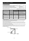
4.2.23 PID function
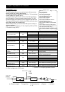
The PID function allows you to use the inverter for the process
control on fluid flow, airflow, and pressure.
To enable this function, specify "01 lenabled" or "02 inverted data
output enabled" for function "A071".
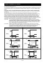
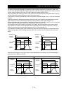
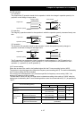
You can disable the PID function with an external signal during
the PID operation. For this purpose, assign function "23" (PID
terminal: disabling PID operation) to an intelligent input terminal.
Turning the PID terminal on disables the PID function and makes
the inverter perform the normal output.
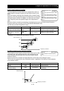
With the PID function, you can limit the PID output according to
various conditions.
Refer to maximum frequency (4.2.10), frequency limiter (4.2.20),
PID rariation range (A078).
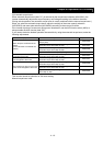
Item Function code Data or range of data Description
00 Disabling the PID operation
01 Enabling the PID operation
PID Function Enable A071
02 Enabling inverted-data output
PID proportional gain A072 0.2 to 5.0 Proportional gain
PID integral time constant A073 0.0 to 3600.(s) Integrated gain
PID derivative gain A074 0.00 to 100.0(s) Derivative gain
PV scale conversion A075 0.01 to 99.99
Scale for unit conversion of PID feedback
data
00 OI-L: 4 to 20 mA
01 O-L: 0 to 10 V
02 RS485 communication
03 Frequency command as pulse train
PV source setting A076
10 Operation result (*1)
00 Disabling the inverted output
Output of inverted PID
deviation
A077
01
Enabling the inverted output (deviation
polarity inverted)
PID variation range A078 0.0 to 100.0(%)
Range of PID data variation with
reference to the target value
00 Invalid
01 O-L : 0-10V
02 OI-L : 4-20mA
PID feed forward selection A079
03 O2-L : -10-10V
PID deviation level setting C044 0.0 to 100.0(%) Level to determine the OD signal output
Off level of feedback
comparison signal
C052 0.0 to 100.0(%) Level to determine the FBV signal output
Onlevel of feedback
comparison signal
C053 0.0 to 100.0(%) Level to determine the FBV signal output
(*1) refer 4.2.12 Frequency operation function
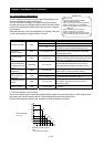
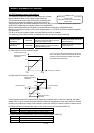
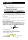
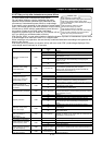
(1) Basic configuration of PID control
Kp: Proportional gain Ti: Integral time Td: Derivative time s: Operator ε: Deviation
fs
M
=
+
-
Kp(1+ +Td・S)
1
Ti・S
Target value
0 to 10 V
4 to 20 mA
Deviation
(ε)
Feedback 0 to 10 V
4 to 20 mA
Operation
quantity
Normal control
by the inverter
Transducer
Sensor
+
+
Feed Forward invalid
0-10V
0-20mA
-10-10V
A001: Frequency source setting
A005: [AT] selection
A006: [O2] selection
A071: PID Function Enable
A072: PID proportional gain
A073: PID integral time constant
A074: PID derivative gain
A075: PV scale conversion
A076: PV source setting
A077: Output of inverted PID deviation
A078: PID variation range
A079: PID feed forward selection
d004: Process variable (PV), PID feedback
monitoring
C001 to C008: Terminal [1] to [8] functions
C021 to C025: Terminal [11] to [15] functions
C044: PID deviation level setting
C052: Off level of feedback comparison signal
C053: Onlevel of feedback comparison signal
Related code