


Chapter 4 Explanation of Functions
4 - 2
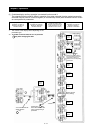
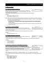
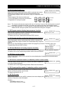
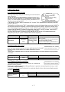
4.1.5 Intelligent input terminal status
When the intelligent input terminal status function (d005) is selected, the
inverter displays the states of the inputs to the intelligent input terminals.
The internal CPU of the inverter checks each intelligent input for significance, and the inverter displays
active inputs as those in the ON state. (*1)
Intelligent input terminal status is independent of the a/b contact selection for the intelligent input terminals.
(Example)
FW terminal and intelligent input terminals [7], [2], and [1]: ON
Intelligent input terminals [8], [6], [5], [4], and [3]: OFF
(*1)When input terminal response time is set, terminal recognition is delayed. (refer 4.2.79)
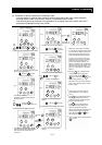
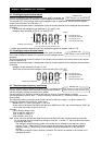
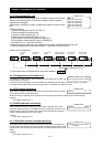
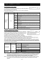
4.1.6 Intelligent output terminal status
When the intelligent output terminal status function (d006) is selected,
the inverter displays the states of the outputs from the intelligent output
terminals.
This function does not monitor the states of the control circuit terminals but monitors those of the outputs
from the internal CPU.
Intelligent input terminal status is independent of the a/b contact selection for the intelligent input terminals.
(Example)
Intelligent output terminals [12] and [11]: ON
Alarm relay terminal AL and intelligent output terminals [15] to [13]: OFF
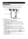
4.1.7 Scaled output frequency monitoring
When the scaled output frequency monitoring (d007) is selected, the
inverter displays the gain data converted from the output frequency
with the frequency scaling conversion factor (b086).
Use this function, for example, to change the unit of a value (e.g., motor speed) on display.
Value displayed by function "d007" = "output frequency monitor(d001)" x "frequency scaling conversion
factor (b086)"
The frequency scaling conversion factor (b086) can be set within the range 0.1 to 99.9 in steps of 0.1.
(Example) Displaying the speed of a 4-pole motor
Speed N (min
-1
) = (120 x f [Hz])/pole = f (Hz) x 30
As the result of the above calculation with the factor (b086) set to 30.0, the inverter displays "1800" (60
x 30.0) when the output frequency is 60 Hz.
(Display)
0.00 to 99.99 in steps of 0.01
100.0 to 999.9 in steps of 0.1
1000. to 9999. in steps of 1
1000 to 3996 in units of 10
Note: When you have selected the digital operator as the device to input frequency-setting commands,
you can change the output frequency setting by using the △ and/or ▽ key (only while the inverter
is operating the motor).
- The change in output frequency made in this mode can be reflected in the frequency setting
(function "F001"). Press the STR key to write the new frequency over the currently selected
frequency setting. (The precision of the storable frequency data depends on the frequency
setting.)
- You cannot change the output frequency while the PID function is enabled or the inverter is not
operating the motor.
ON
ON
OFF
FW
OFF
1
(ON)
2
(ON)
3
(OFF)
4
(OFF)
5
(OFF)
6
(OFF)
7
(ON)
8
(OFF)
Display
: The segment is on,
indicating the ON state.
: The segment is off,
indicating the OFF state.
Intelligent input terminals
ON
OFF
11
(ON)
12
(ON)
13
(OFF)
14
(OFF)
15
(OFF)
AL
(OFF)
Display
: The segment is on,
indicating the ON state.
: The segment is off,
indicating the OFF state.
Intelligent input terminals
d005: Intelligent input terminal status
Related code
d006: Intelligent output terminal status
Related code
d007: Scaled output frequency monitoring
b086: Frequency scaling conversion factor
Related code