


Chapter 2 Installation and Wiring
2 - 17
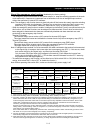
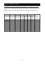
(4) Recommended cable gauges, wiring accessories, and crimp terminals
Note: For compliance with CE and UL standards, see the safety precautions concerning EMC and the
compliance with UL and CUL standards under Safety Instructions.
The table below lists the specifications of cables, crimp terminals, and terminal screw tightening
torques for reference.
Applicable device
Motor
output
(kW)
Applicable inverter
model
Gauge of power
line cable (mm
2
)
(Terminals: R, S,
T, U, V, W, P, PD,
and N)
Grounding
cable (mm
2
)
External braking
resistor across
terminals P and
RB (mm
2
)
Size of
terminal
screw
Crimp
terminal
Tightening
torque
(N-m)
Earth-leakage
breaker (ELB)
Magnetic
contactor
(MC)
5.5 SJ700-055LFF2
5.5 5.5 5.5 M5 R5.5-5
2.4 EX50B (50A) HK25
7.5 SJ700-075LFF2
8 8 8 M5 R8-5 2.4 EX60 (60A) HK35
11 SJ700-110LFF2
14 14 14 M6 R14-6
4.5 RX100 (75A) HK50
15 SJ700-150LFF2
22 22 22 M6 22-6 4.5 RX100 (100A)
H65
18.5 SJ700-185LFF2
30 22 30 M6
30-S6
38-8
4.5 RX100 (100A)
H80
22 SJ700-220LFF2
38 30 38 M8
38-S8
38-10
8.1 RX225B (150A)
H100
30 SJ700-300LFF2
60 (22×2) 30 ― M8
60-S8
60-10
CB60-8
CB60-S8
8.1 RX225B (200A)
H125
37 SJ700-370LFF2
100 (38×2) 38 ― M8 100-8
8.1 RX225B (225A)
H150
45 SJ300-450LFF2
100 (38×2) 38 ― M8 100-8
8.1 RX225B (225A)
H200
200 V class
55 SJ300-550LFF2
150 (60×2) 60 ― M10 150-10
8.1 RX400B (350A)
H250
5.5 SJ700-055HFF2
2 2 2 M5 R2-5 2.4 EX50C (30A) HK20
7.5 SJ700-075HFF2
3.5 3.5 3.5 M5 3.5-5
2.4 EX50C (30A) HK25
11 SJ700-110HFF2
5.5 5.5 5.5 M6 R5.5-6
4.5 EX50C (30A) HK35
15 SJ700-150HFF2
8 8 8 M6 8-6 4.5 EX60B (60A) HK35
18.5 SJ700-185HFF2
14 14 14 M6 14-6 4.5 EX60B (60A) HK50
22 SJ700-220HFF2
14 14 14 M6 14-6 4.5 RX100 (75A) HK50
30 SJ700-300HFF2
22 22 ― M6 22-6 4.5 RX100 (100A)
H65
37 SJ700-370HFF2
38 22 ― M8 38-8 8.1 RX100 (100A)
H80
45 SJ700-450HFF2
38 22 ― M8 38-8 8.1 RX225B (150A)
H100
400 V class
55 SJ700-550HFF2
60 30 ― M8 R60-8
8.1 RX255B (175A)
H125
Note: Cable gauges indicate those of HIV cables (maximum heat resistance: 75°C).
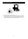
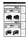
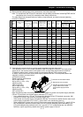
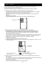
(5) Connecting the control circuit to a power supply separately from the main circuit
If the protective circuit of the inverter operates to open the magnetic contactor in the input power
supply circuit, the inverter control circuit power is lost, and the alarm signal cannot be retained.
To retain the alarm signal, connect control circuit terminals R0 and T0 to a power supply.
In details, connect the control circuit power supply terminals R0 and T0 to the primary side of the
magnetic contactor as shown below.
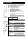
(Connection method)
Power-receiving specifications
200 V class model:
200 to 240 V (+10%, -15%)
(50/60 Hz ±5%)
(282 to 339 VDC)
400 V class model:
380 to 480 V (+10%, -15%)
(50/60 Hz ±5%)
(537 to 678 VDC)
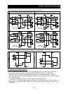
Note the following when connecting separate power supplies to control circuit power supply terminals
(R0 and T0) and main circuit power supply terminals (R, S, and T):
- Use a cable thicker than 1.25 mm
2
to connect the terminals R0 and T0 (terminal screw size: M4).
- Connect a 3 A fuse in the control circuit power supply line.
- If the control circuit power supply (connected to R0 and T0) is turned on earlier than the main circuit
power supply (connected to R, S, and T), ground fault is not checked at power-on.
- When supplying DC power to the control circuit power supply terminals (R0 and T0), specify "00" as
the "a/b (NO/NC)" selection (function code C031 to C036) for intelligent output terminals ([11] to
[15]) and intelligent relay terminals (AL0, AL1, and AL2). If "01" is specified as the "a/b (NO/NC)"
selection, output signals may chatter when the DC power supply is shut off.
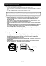
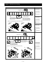
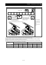
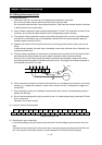
② Remove the J51 connector.
① Remove the connected cables.
③
Connect the control circuit power
supply cables to the control
circuit power supply terminal
block.
J51