


Chapter 4 Explanation of Functions
4 - 94
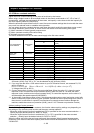
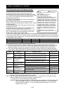
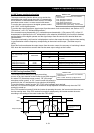
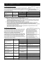
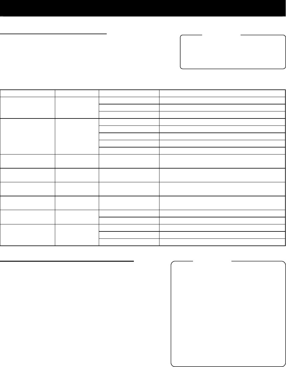
4.2.102 Torque LAD stop function
The torque LAD stop function is effective when "03" (sensorless
vector control), "04" (0Hz-range sensorless vector control), or
"05" (vector control with sensor) is specified for the V/F
characteristic curve selection (A044/A244). This function
temporarily stops the frequency-based deceleration function
(LAD) when the torque limitation function operates.
Item Function code Data or range of data Description
03 Sensorless vector control
04 0Hz-range sensorless vector control
V/F characteristic
curve selection
A044/A244
05 Vector control with sensor (not available for A244)
00 Quadrant-specific setting mode
01 Terminal-switching mode
02 Analog input mode
03 Option 1 mode
Torque limit
selection
b040
04 Option 2 mode
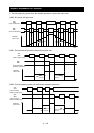
Torque limit (1) b041 0 to 200 (%)
Forward powering (in quadrant-specific setting
mode)
Torque limit (2) b042 0 to 200 (%)
Reverse regeneration (in quadrant-specific
setting mode)
Torque limit (3) b043 0 to 200 (%)
Reverse powering (in quadrant-specific setting
mode)
Torque limit (4) b044 0 to 200 (%)
Forward regeneration (in quadrant-specific
setting mode)
00 Disabling the torque LAD stop function Torque limit
LADSTOP enable
b045
01 Enabling the torque LAD stop function
40 Whether to enable torque limitation
41 Torque limit switch 1
Terminal function C001 to C008
42 Torque limit switch 2
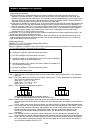
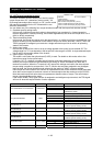
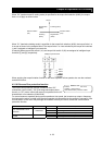
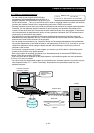
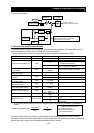
4.2.103 High-torque multi-motor operation
The high-torque multi-motor operation function allows you to
make a single inverter operate the two motors (having the
same specifications) that drive a single load (machine). This
function is effective when the V/F characteristic curve selection
is the sensorless vector control or 0Hz-range sensorless
control.
To use the function, adjust the inverter settings required for the
sensorless vector control (see Section 4.2.92) or 0Hz-range
sensorless control (see Section 4.2.93), except for the motor
constant settings. Adjust the motor constants as follows:
1) For constants R1, R2, and L, specify a value half as large
as that normally specified for one motor.
2) For constant Io, specify a value twice as large as that
normally specified for one motor.
3) For constant J, specify a value half as large as the total
moment of inertia of the two motors and the load connected
to them.
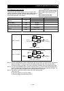
Select the motor capacity that is closest to the collective capacity of both motors.
If different loads are driven by the two motors operated by the inverter, the load fluctuations on one motor
may change the other motor's operation status, and the inverter may be unable to normally control the
motors. Be sure to configure your system so that the motors drive only a single load or multiple loads that
can, at least, be recognized as a single load.
A044/A244: V/F characteristic curve selection,
1st/2nd motors
b040: Torque limit selection
b041 to b044: Torque limits (1) to (4)
b045: Torque limit LADSTOP enable
Related code
A044/A244: V/F characteristic curve selection,
1st/2nd motors
F001: Output frequency setting
b040: Torque limit selection
b041 to b044: Torque limits (1) to (4)
H002/H202: Motor data selection, 1st/2nd motors
H003/H203: Motor capacity, 1st/2nd motors
H004/H204: Motor poles setting, 1st/2nd motors
H005/H205: Motor speed constant, 1st/2nd motors
H020/H220: Motor constant R1, 1st/2nd motors
H021/H221: Motor constant R2, 1st/2nd motors
H022/H222: Motor constant L, 1st/2nd motors
H023/H223: Motor constant Io, 1st/2nd motors
H024/H224: Motor constant J, 1st/2nd motors
H050/H250: PI proportional gain, 1st/2nd motors
H051/H251: PI integral gain, 1st/2nd motors
H052/H252: P proportional gain setting, 1st/2nd
motors
Related code