


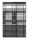


Chapter 5 Error Codes
5 - 2
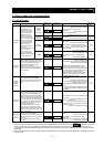
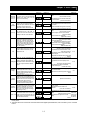
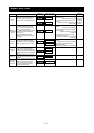
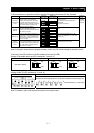
Under.V
CT
CPU
EXTERNAL
USP
GND.Flt
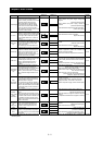
OV.SRC
Inst.P-F
OH.stFAN
OH.fin
Name Description
Display on
digital operator
Display on
remote operator
Troubleshooting and corrective action
Referen
ce page
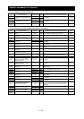
Undervoltage
If the inverter input voltage drops, the
control circuit of the inverter cannot
function normally. Therefore, the inverter
shuts off its output when the input
voltage falls below a specified level.
The inverter will trip if the DC voltage
across the P and N terminals exceeds
about 175 VDC (in case of the 200 V
class models) or about 345 VDC (in case
of the 400 V class models).
Check whether the power supply voltage has
dropped.
(Check the power supply.)
Check whether the power supply capacity is
sufficient.
(Check the power supply.)
Check whether the thyristor has been damaged.
(Check the thyristor.)
4-25
CT error
If an error occurs in the internal current
detector (CT), the inverter will shut off its
output and display the error code shown
on the right. The inverter will trip when
the CT outputs about 0.6 V or more at
power-on.
Check whether the inverter has failed.
(Repair the inverter.)
-
CPU error
(*3)
If the internal CPU malfunctions or an
error occurs in it, the inverter will shut off
its output and display the error code
shown on the right.
Note: Reading an abnormal data from
the EEPROM may result in a CPU error.
Check for the noise sources located near the
inverter.
(Remove noise sources.)
Check whether the inverter has failed.
(Repair the inverter.)
-
External trip
If an error occurs in the external
equipment or device connected to the
inverter, the inverter will fetch the error
signal and shut off its output. (This
protective function is enabled when the
external trip function is enabled.)
Check whether an error has occurred in the
external equipment (when the external trip
function has been enabled).
(Recover the external equipment from the error.)
4-56
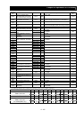
USP error
A USP error is indicated when the
inverter power is turned on with an input
operation signal remaining in the
inverter. (This protective function is
enabled when the USP function is
enabled.)
Check whether the inverter power has been
turned on with an input operation signal remaining
in the inverter (when the USP function has been
enabled).
(Reset the operation command, and then turn on
the inverter power.)
4-55
Ground-fault
protection
(*3)
When the inverter power is turned on,
this protective function detects the
ground fault between the inverter output
circuit and the motor to protect the
inverter. (This function does not operate
when a residual voltage remains in the
motor.)
Check for the ground fault.
(Check the output cables and motor.)
Check the inverter itself for abnormality.
(Remove the output cables from the inverter, and
then check the inverter.)
Check the main circuit for abnormality.
(Check the main circuit with reference to
Chapter 6.) (Repair the inverter.)
-
Input
overvoltage
protection
This protective function determines an
error if the input voltage is kept above
the specification level for 100 seconds
while the inverter is stopped.
The inverter will trip if the DC voltage of
the main circuit is kept above about 380
VDC (in case of the 200 V class models)
or about 760 VDC (in case of the 400 V
class models).
Check whether the input voltage is high while the
inverter is stopped.
(Lower the input voltage, suppress the power
voltage fluctuation, or connect an AC reactor
between the power supply and the inverter input.)
-
Instanta-
neous power
failure
protection
If an instantaneous power failure lasts 15
ms or more, the inverter will shut off its
output.
When the power failure duration is long,
the inverter assumes a normal power-off.
If a restart mode has been selected and
an operation command remains in the
inverter, the inverter will restart after the
power is recovered.
Check whether the power supply voltage has
dropped.
(Recover the power supply.)
Check the MCB and magnetic contactors for poor
contacts.
(Replace the MCB and the magnetic contactor.)
4-34
Temperature
error due to
low
cooling-fan
speed
The inverter will display the error code
shown on the right if the lowering of
cooling-fan speed is detected at the
occurrence of the temperature error
described below.
Check whether the cooling efficiency has been
lowered.
(Replace the cooling fan.)
Check the heat sink for clogging.
(Clean the heat sink.)
-
Temperature
error
If the main circuit temperature rises
because of a high ambient temperature
or for other reasons, the inverter will shut
off its output.
Check whether the inverter is installed vertically.
(Check the installation.)
Check whether the ambient temperature is high.
(Lower the ambient temperature.)
-
*3 The inverter will not accept reset commands input via the RS terminal or entered by the STOP/RESET key. Therefore, turn off the
inverter power.