


Chapter 4 Explanation of Functions
4 - 4
4.1.14 Cumulative power monitoring
When the cumulative power monitoring function is selected, the inverter
displays the cumulative value of electric power input to the inverter.
You can also convert the value to be displayed to gain data by setting
the cumulative input power display gain setting (b079).
Value displayed by function "d015" = "calculated value of input power (kW/h)"/"cumulative input power
display gain setting (b079)"
The cumulative power input gain can be set within the range 1 to 1000 in steps of 1.
You can clear the cumulative power data by specifying "01" for the cumulative power clearance function
(b078) and pressing the STR key.
You can also clear the cumulative power data at an intelligent input terminal by assigning function "53"
(KHC: cumulative power clearance) to the intelligent input terminal.
When the cumulative input power display gain setting (b079) is set to "1000", the cumulative power data
up to 999000 (kW/h) can be displayed.
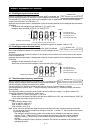
(Display)
0.0 to 999.9 in steps of 1 kW/h, or the unit set for function "b079"
1000 to 9999 in units of 10 kW/h, or the unit set for function "b079"
⎡100 to ⎡999 in units of 1000 kW/h, or the unit set for function "b079"
4.1.15 Cumulative operation RUN time monitoring
When the cumulative operation RUN time monitoring function (d016) is
selected, the inverter displays the cumulative time of the inverter
operation.
(Display)
0. to 9999. in units of 1 hour
1000 to 9999 in units of 10 hours
⎡100 to ⎡999 in units of 1,000 hours
4.1.16 Cumulative power-on time monitoring
When the cumulative power-on time monitoring function(d017) is selected,
the inverter displays the cumulative time throughout which the inverter
power has been on.
(Display)
0. to 9999. in units of 1 hour
1000 to 9999 in units of 10 hours
⎡100 to ⎡999 in units of 1,000 hours
4.1.17 Heat sink temperature monitoring
When the heat sink temperature monitoring function (d018) is selected,
the inverter displays the temperature of the internal heat sink of the
inverter.
(Display)
0.0 to 200.0 in steps of 0.1 °C
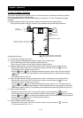
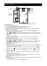
4.1.18 Motor temperature monitoring
When the motor temperature monitoring function is selected, the inverter
displays the temperature of the thermistor connected between control
circuit terminals TH and CM1.
Use the thermistor model PB-41E made by Shibaura Electronics Corporation.
Specify "02" (enabling NTC) for the thermistor for thermal protection control (function "b098").
(Display)
0.0 to 200.0 in steps of 0.1 °C.
Note: If "01" (enabling PTC) is specified for the thermistor for thermal protection control (function "b098"),
motor temperature monitoring is disabled.
d015: Cumulative power monitoring
b078: Cumulative power clearance
b079: Cumulative input power display
gain setting
Related code
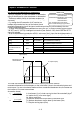
d016: Cumulative operation RUN time
monitoring
Related code
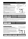
d017: Cumulative power-on time
monitoring
Related code
d019: Motor temperature monitoring
b098: Thermistor for thermal
protection control
Related code
d018: Heat sink temperature
monitoring
Related code