


Chapter 4 Explanation of Functions
4 - 74
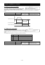
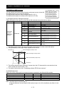
4.2.82 AM and AMI terminals
You can monitor the inverter output frequency and output current via the AM
and AMI terminals on the control circuit block.
The AM terminal outputs an analog voltage signal (0 to 10 V).
The AMI terminal outputs an analog current signal (4 to 20 mA).
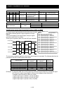
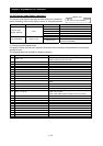
(1) AM siginal selection /AMI signal selection
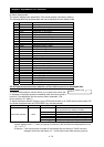
Select the signals to be output from the AM and AMI terminals among those shown below.
Item Function code Data Description Full-scale value
00 Output frequency 0 to maximum frequency (Hz) (*3)
01 Output current 0 to 200%
02 Output torque (*1) 0 to 200%
04 Output voltage
0 to 133% (75% of full scale is
equivalent to 100%)
05 Input power 0 to 200%
06
Electronic thermal
overload
0 to 100%
07 LAD frequency 0 to maximum frequency (Hz)
09 Motor temperature
0ºC to 200ºC (0ºC is output when the
motor temperature is 0ºC or less.)
10 Heat sink temperature
0ºC to 200ºC (0ºC is output when the
motor temperature is 0ºC or less.)
11 Output torque (signed)
(Output only from the AM terminal) 0
to 200% (*1) (*2)
13 General analog YA (1) (*4)
(Output only from the AM terminal) 0
to 100%
[AM] siginal
selection /
[AMI] siginal
selection
C028/C029
14 General analog YA (2) (*4)
(Output only from the AMI terminal) 0
to 100%
*1 This signal is output only when the V/F characteristic curve selection (see Section 4.2.18) is the
sensorless vector control, 0Hz-range sensorless vector control, or vector control with sensor.
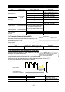
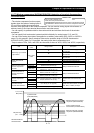
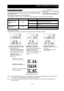
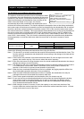
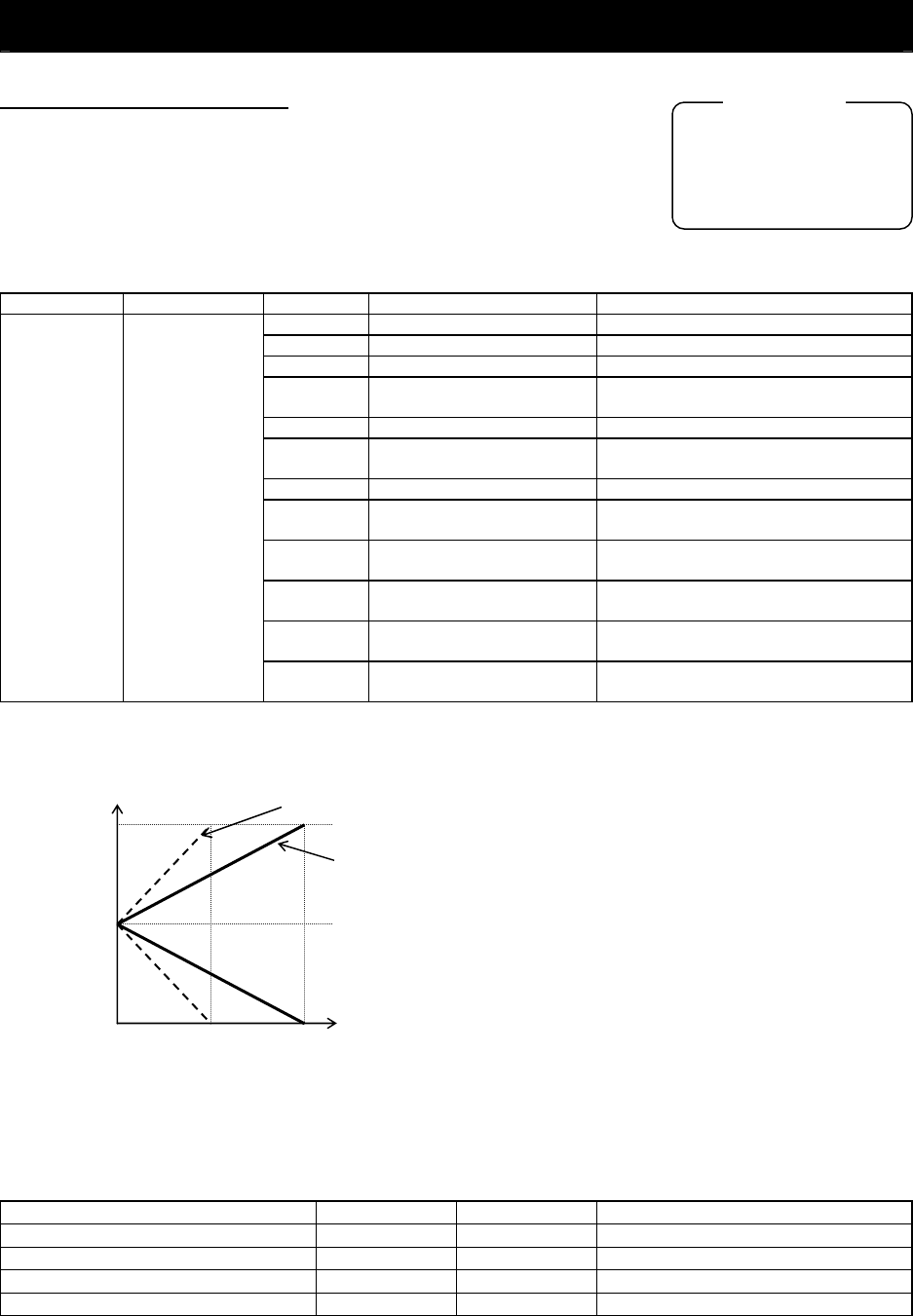
*2 The specifications of the output torque (signed) are as follows:
*3 The actually detected output frequency is output when the V/F characteristic curve selection is the
vector control with sensor (A044 = 05).
*4 For detail of the function, refer “Programing software EZ-SQ user manuaru”.
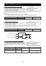
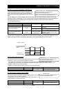
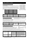
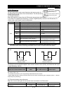
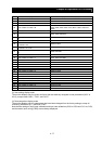
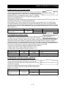
(2) AM/AMI adjustment
Adjust the inverter output gain for the external meters connected to the AM and AMI terminals.
Item Function code Range of data Description
Setting of the gain for AM monitoring C106 50. to 200. (%) Setting of the gain for AM monitoring
Setting of the offset for AM monitoring C109 0 to 100 (%) Setting of the offset for AM monitoring
Setting of the gain for AMI monitoring C107 50. to 200. (%) Setting of the gain for AMI monitoring
Setting of the offset for AMI monitoring C110 0 to 100 (%) Setting of the offset for AMI monitoring
Note: The offset data is in percentage (%).
(Example) When the current range of AMI terminal output is 4 to 20 mA (default), the offset of 4 mA
is 20%.
C028: [AM] siginal selection
C029: [AMI] siginal selection
C106: AM gain adjustment
C109: AM offset adjustment
C108: AMI gain adjustment
C110: AMI offset adjustment
Related code
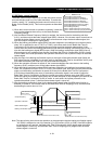
200 100
10
5
0
AM output (V)
When the AM gain (C106) is 100%
When the AM gain (C106) is 200%
When the AM offset (C109) is 50%
Torque (%)