


Chapter 4 Explanation of Functions
4 - 10
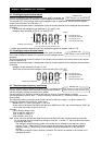
4.2.8 Acceleration/deceleration time setting
- Specify a longer time for slower acceleration or deceleration;
specify a shorter time for quicker acceleration or deceleration.
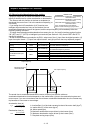
- The time set with this function is the time to accelerate (or
decelerate) the motor from 0 Hz to the maximum frequency (or
vice versa).
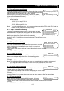
- If you assign the LAD cancellation (LAC) function to an
intelligent input terminal and turns on the terminal, the set
acceleration/deceleration time will be ignored, and the output frequency will immediately follow the
frequency-setting command.
- To switch the acceleration and deceleration time among the 1st, 2nd, and 3rd settings, assign function
"08" (SET) and "17" (SET3) to intelligent input terminals (see Section 4.2.38). Use the SET and SET3
signals for switching.
- As the Accel/decel time input selection by P031, select one of the (1) input from the digital operation, (2)
input from option board 1, (3) input from option board 2, and (4) input from the easy sequence program.
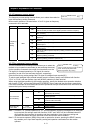
Item Function code Range of data Description
Acceleration (1) time
setting
F002/F202/
F302
0.01 to 3600.(s)
Set the length of time to accelerate the motor from 0
Hz to the maximum frequency.
Deceleration (1) time
setting
F003/F203/
F303
0.01 to 3600.(s)
Set the length of time to decelerate the motor from
the maximum frequency to 0 Hz.
00 Input from the digital operator (OPE)
01 Input from option board 1 (OP1)
02 Input from option board 1 (OP2)
Accel/decel time input
selection
P031
03 Input from the easy sequence program (PRG)
Terminal function C001 to C008 46 LAD cancellation
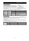
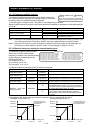
The actual time to accelerate/decelerate the motor will be no less than the minimum
acceleration/deceleration time that depends on the inertial effect (J) due to the mechanical system and
motor torque. If you set a time shorter than the minimum acceleration/deceleration time, the inverter may
trip because of overcurrent or overvoltage.
J
L
: Inertia effect (J) of the load converted to that of the motor shaft (kg-m
2
)
J
M
: Inertia effect (J) of the motor (kg-m
2
)
N
M
: Motor speed (rpm)
Ts: Maximum acceleration torque driven by the inverter (N-m)
T
B
: Maximum deceleration torque driven by the inverter (N-m)
T
L
: Required running torque (N-m)
F002/F202/F302: Acceleration (1) time setting,
1st/2nd/3rd motors
F003/F203/F303: Deceleration (1) time setting,
1st/2nd/3rd motors
A004/A204/A304: Maximum frequency setting,
1st/2nd/3rd motors
P031: Accel/decel time input selection
C001 to C008: Terminal [1] to [8] functions
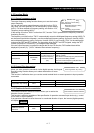
Related code
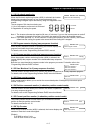
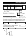
Maximum frequency
A
004/A204/A304
F002/F202/F302 F003/F203/F303
Output frequency
Set output frequency
Actual
acceleration
time
Actual
deceleration
time
Acceleration time (ts)
Deceleration time (t
B
)
t
s
=
(J
L
+J
M
)×N
M
9.55×(T
s
-T
L
)
t
B
=
(J
L
+J
M
)×N
M
9.55×(T
B
+T
L
)