


Reference Manual
00809-0100-4530, Rev BA
July 2009
Rosemount 5300 Series
5-46
7. Configure Tri-Loop Channel 1:
a. Assign variable: Tri-Loop HART command [1,2,2,1,1].
Make sure that the SV, TV, and QV match the configuration of the
5300 transmitter.
b. Assign units: Tri-Loop HART command [1,2,2,1,2]. Make sure that
the same units are used as for the 5300 transmitter.
c. Set the Upper Range Value and the Lower Range Value: Tri-Loop
HART command [1,2,2,1,3-4].
d. Enable the channel. Tri-Loop HART command [1,2,2,1,5].
8. (Optional) Repeat steps a-d for Channels 2 and 3.
9. Connect wires to Tri-Loop Burst Input.
10. Enter the desired tag, descriptor, and message information:
Tri-Loop HART command [1,2,3].
11. (Optional) If necessary, perform an analog output trim for Channel 1 (and
Channel 2 and 3 if they are used).
Tri-Loop HART command [1,1,4].
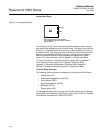
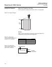
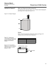
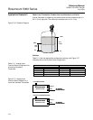
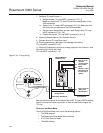
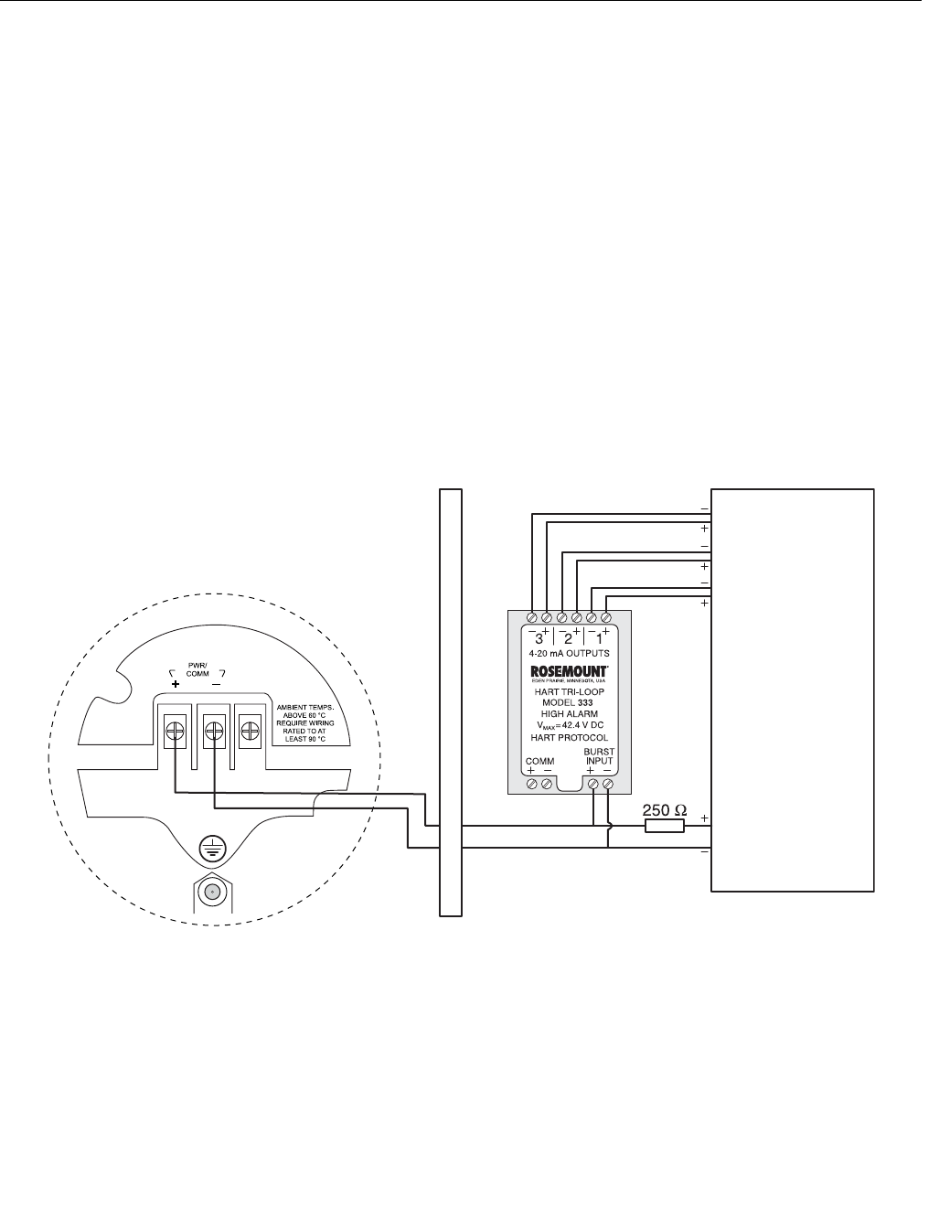
Figure 5-18. Tri-Loop wiring.
See the reference manual for the Model 333 HART Tri-Loop HART-to-Analog
Signal Converter for further information on how to install and configure the
Tri-Loop.
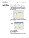
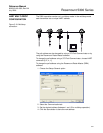
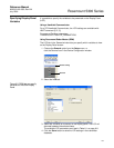
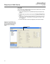
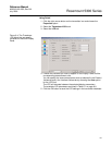
To turn off the Burst Mode
To turn off the Burst Mode, use one of the following options:
• The RRM program
• The Rosemount Burst Mode Switch software
• A 375 Field Communicator
• The AMS software
Each Tri-Loop
Channel
receives power
from Control
Room
Channel 1 must
be powered for
the Tri-Loop to
operate
Device receives
power from
Control Room
HART Burst Command 3/
Analog Output
Intrinsically Safe Barrier
DIN Rail Mounted
HART Tri-Loop
Control Room
QV
TV
SV
PV