


Reference Manual
00809-0100-4530, Rev BA
July 2009
Rosemount 5300 Series
4-6
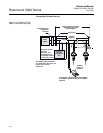
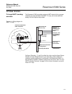
Non-Intrinsically Safe
Output
With non-intrinsically safe power supply in non-hazardous installations or
Explosion-proof/Flameproof installations, wire the transmitter as shown in
Figure 4-5.
NOTE!
Make sure that the power supply is off when connecting the transmitter.
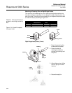
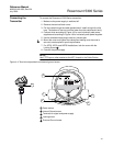
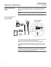
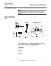
Figure 4-5. Wiring diagram for
non-intrinsically safe
installations (HART).
For HART communication a minimum load resistance of 250 within the loop
is required. For maximum load resistance. See Figure 4-1
(Explosion/Flameproof) and Figure 4-2 (Non-hazardous installations).
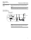
For Explosion-proof/Flameproof applications the resistance between the
negative terminal on the transmitter and the power supply must not exceed
435 Ohm.
NOTE!
For Explosion-proof/Flameproof installations, make sure the transmitter is
grounded to the internal ground terminal inside the terminal compartment in
accordance with national and local electrical codes.
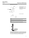
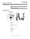
Load Resistance
Power
Supply
375 Field
Communicator
Rosemount 5300 Series
Radar Transmitter
HART modem
RRM
AMS Suite
250