


Reference Manual
00809-0100-4530, Rev BA
July 2009
Rosemount 5300 Series
www.rosemount.com
Appendix F Level Transducer Block
Overview . . . . . . . . . . . . . . . . . . . . . . . . . . . . . . . . . . . . . . . page F-1
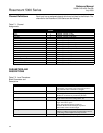
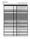
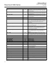
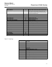
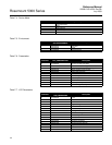
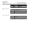
Parameters and Descriptions . . . . . . . . . . . . . . . . . . . . . . page F-2
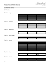
Supported Units . . . . . . . . . . . . . . . . . . . . . . . . . . . . . . . . . page F-8
Diagnostics Device Errors . . . . . . . . . . . . . . . . . . . . . . . . . page F-9
OVERVIEW This section contains information on the 5300 Level Transducer Block (TB).
Descriptions of all Transducer Block parameters, errors, and diagnostics are
listed.
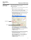
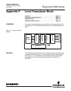
Figure F-1. Transducer Block
Diagram
Definition The transducer block contains the actual measurement data, including a level
and distance reading. Channels 1–16 are assigned to these measurements
(see Figure F-1). The transducer block includes information about sensor
type, engineering units, and all parameters needed to configure the
transmitter.
Digital
Signal
Conversion
Diagnostics
Linearization
Temperature
Compensation
Damping
Units/Ranging
Channel
1
TB
2
3
4
5
6
Channel
Channel
Channel
Channel
Channel