


Reference Manual
00809-0100-4530, Rev BA
July 2009
7-11
Rosemount 5300 Series
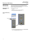
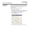
The Configuration Mode
Tab
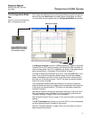
The Configuration Mode tab lets you adjust the different amplitude thresholds.
When clicking the Echo Curve icon under Device Config/Setup, the Echo
Curve Analyzer window appears with the Configuration Mode tab selected:
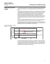
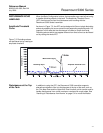
Figure 7-9. Echo Curve Analyzer
plot in Configuration mode.
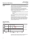
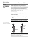
The Measure and Learn function in RRM automatically creates an Amplitude
Threshold Curve (ATC) which is used by the Rosemount 5300 transmitter to
find the surface pulse. The ATC is adapted to the shape of the measurement
signal as described in “Disturbance Echo Handling” on page 7-7.
To create an Amplitude Threshold Curve (ATC), click the Learn button in the
Echo Curve Analyzer/Configuration Mode window. By clicking the Learn
button, the Measure and Learn function is activated, which creates an ATC
that filters out all disturbing echoes. The ATC can also be manually edited if
further fine tuning is needed.
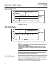
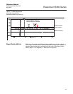
The Configuration Mode window also allows you to manually change the
amplitude thresholds simply by dragging the corresponding anchoring points
in the plot to the desired positions. This option can be used to change the
Interface Threshold.
Note that by manually changing the amplitude thresholds in the Echo Curve
plot, the Automatic mode is disabled for the corresponding threshold (see
“Threshold Settings” on page C-8 for more information).
See “Surface Pulse Not Found” on page 7-5 for more information on threshold
settings.
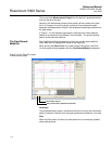
The Set Thresholds button allows you to set the ATC to a fixed value based
on the configured Dielectric Constant of the product.
See also “Threshold Settings” on page C-8 for more information on how to
adjust amplitude thresholds.
Set threshold
Measure and Learn
See the RRM online-help for
descriptions of the various
display options in the Echo
Curve Analyzer window.
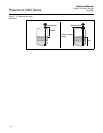
Measurement Output