


Reference Manual
00809-0100-4530, Rev BA
July 2009
7-33
Rosemount 5300 Series
DIAGNOSTIC
MESSAGES
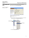
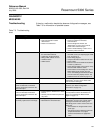
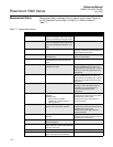
Troubleshooting If there is a malfunction despite the absence of diagnostic messages, see
Table 7-3 for information on possible causes.
Table 7-3. Troubleshooting
chart
Symptom Possible cause Action
No level reading
• Power disconnected
• Data communication cables
disconnected
• Probe is not connected
• Check the power supply
• Check the cables for serial data
communication
• View the Diagnostic window, see
“Diagnostics” on page 7-23 in order to
check active status messages
• Check if “Probe Missing” is active. If it is,
check the probe connection
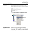
No HART communication.
• COM Port configuration does not match
the connected COM Port
• Cables may be disconnected
• Wrong HART address is used
• Hardware failure
•HART resistor
• Check that correct COM Port is selected in
the HART server (see “Specifying the COM
Port” on page 5-15
• Check wiring diagram
• Verify that the 250 resistor is in the loop.
• Check cables
• Make sure that correct HART short address
is used. Try address=0
• Check Analog Output current value to verify
that transmitter hardware works
• Check that the correct settings are used in
RRM. Select Device, Search from the
menu. Click Settings and HART tab. Make
sure the values are properly chosen. The
standard values are shown on page 5-10
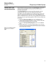
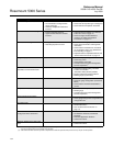
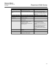
Analog Out is set in Alarm. Measurement or transmitter failure. View the Diagnostic window, see
“Diagnostics” on page 7-23 to check active
error and status messages.
Both Surface pulse and Interface
Pulse are detected, but Interface
Level is reported as unknown in the
Echo Curve plot.
Measurement Mode is set to “Level Only”. Set Measurement Mode to “Level and
Interface” (see “Basic Configuration
Parameters” on page 5-4).
Both Surface pulse and Interface
pulse are detected, but Interface
Level is reported as unknown in the
Echo Curve plot.
• Interface pulse is identified as a double
bounce
• Surface pulse and Interface pulse are
very close
No action required. Use the Echo Curve plot
to verify that the surface and interface are
close, see “Analyzing the Measurement
Signal” on page 7-3.
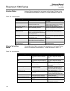
Surface pulse is detected, but Level is
incorrectly reported as Full or Empty.
• Wrong Probe Type set
• Bad Reference Threshold value
View the Diagnostics window, see
“Diagnostics” on page 7-23, to check active
messages and check if the warning “Full
Tank/Empty Tank” is active. If this is the case,
check that:
• the transmitter is configured with correct
probe type
• the reference pulse is below the reference
amplitude threshold. If not, adjust
reference threshold to an appropriate
value