


Reference Manual
00809-0100-4530, Rev BA
July 2009
3-7
Rosemount 5300 Series
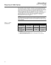
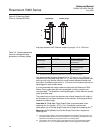
Table 3-2. Pulling force on probe installed in tanks with different products
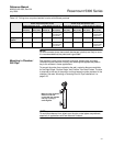
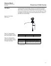
NOTE!
For environments where electrostatic discharges (plastics) are likely to occur,
it is recommended that the probe end is grounded.
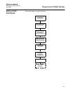
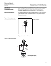
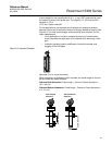
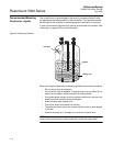
Mounting in Chamber/
Still Pipe
The chamber is also known as bridle, side pipe, bypass pipe, and cage.
Dimensioning the chamber correctly and selecting the appropriate probe is
key to the success in these applications.
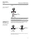
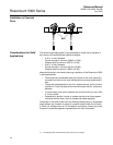
To prevent the probe from contacting the wall, centering discs are available
for the Rigid Single, Flexible Single, and Flexible Twin Lead Probes. The disc
is attached to the end of the probe, and thus keeps the probe centered in the
chamber. See also “Mounting a Centering Disc for Pipe Installations“ on
page 3-25.
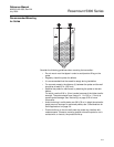
NOTE!
To avoid disturbances from object near the pipe, metal-pipes are preferred,
especially in applications with low dielectric constant.
Material Tensile load for 0.16 in. (4 mm)
flexible single lead probe, lb (kN)
Tensile load for 0.24 in. (6 mm)
flexible single lead probe, lb (kN)
Probe length 49 ft (15 m) Probe length 115 ft (35 m) Probe length 49 ft (15 m) Probe length 115 ft (35 m)
Tank Ø=
10 ft (3 m)
Tank Ø=
39 ft (12 m)
Tank Ø=
10 ft (3 m)
Tank Ø=
39 ft (12 m)
Tank Ø=
10 ft (3 m)
Tank Ø=
39 ft (12 m)
Tank Ø=
10 ft (3 m)
Tank Ø=
39 ft (12 m)
Wheat 670 (3) 1120 (5) 1800 (8) 4500 (20)
Exceeds tensile
strength limit
900 (4) 1690 (7.5) 2810 (12.5) 6740 (30)
Exceeds tensile
strength limit
Polypropylene
Pellets
340 (1.5) 670 (3) 810 (3.6) 2360 (10.5) 450 (2) 920(4.1) 1190 (5.3) 3510 (15.6)
Cement 900 (4) 2020 (9) 2470 (11) 7310 (32.5)
Exceeds tensile
strength limit
1350 (6) 2920 (13) 3600 (16) 10790 (48)
Exceeds tensile
strength limit
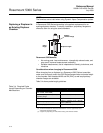
Make sure that the probe
does not come into
contact with the chamber
wall, e.g. by using a
centering disk.