


Reference Manual
00809-0100-4530, Rev BA
July 2009
Rosemount 5300 Series
3-16
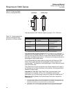
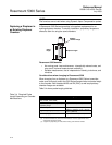
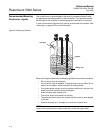
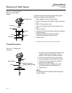
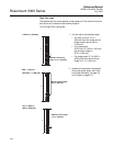
Figure 3-11. Tank connection
with loose flange (“plate
design”).
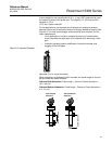
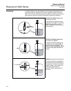
Threaded Connection
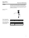
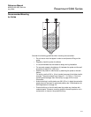
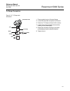
Figure 3-12. Threaded tank
connection.
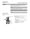
Transmitter head
Gasket
Flange
Tank flange
Probe
Flange nut
Bolts
Nut
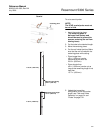
Transmitters delivered with Alloy probes featuring plate
design are mounted as described below:
1. Place a gasket on top of the tank flange.
2. Mount
(1)
the flange on the probe and tighten the flange
nut.
3. Mount
(1)
the transmitter head.
4. Lower the transmitter and probe with flange into the
tank.
5. Tighten the bolts.
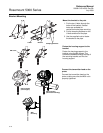
6. Loosen the nut that connects the transmitter housing to
the probe slightly.
7. Rotate the transmitter housing so the cable
entries/display face the desired direction.
8. Tighten the nut.
(1) Flange and transmitter head are normally mounted at the factory.
Sealant on threads or
gasket (for BSP/G threads)
Nut
Tank connection
Probe
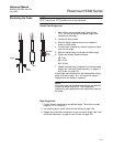
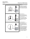
1. For tank connections with BSP/G threads, place
a gasket on top of the tank flange, or use a
sealant on the threads of the tank connection.
2. Lower the transmitter and probe into the tank.
3. Screw the adapter into the process connection.
4. Loosen the nut that connects the transmitter
housing to the probe slightly.
5. Rotate the transmitter housing so the cable
entries/display face the desired direction.
6. Tighten the nut.
NOTE!
For adapters with NPT threads, pressure-tight joints
require a sealant.