


Reference Manual
00809-0100-4530, Rev BA
July 2009
8-5
Rosemount 5300 Series
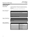
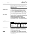
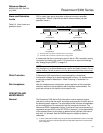
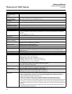
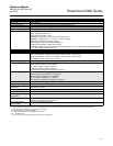
Alarm and Saturation
Levels
DCS or safety logic solver should be configured to match transmitter
configuration. Table 8-3 identifies the alarm levels available and their
operation values.
(1)
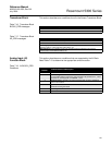
Table 8-3. Alarm levels and
operation values
It is assumed that the current output signal is fed to a SIL2-compliant analog
input board of a safety logic solver. For instructions on alarm level settings
see “Analog Output (HART)” on page 5-9.
NOTE!
Only the High or Low Alarm Mode can be used for the Safety Function. Do not
choose Freeze Current as an error will not be announced in the current loop.
Write Protection A Rosemount 5300 transmitter can be protected from unintentional
configuration changes by a password protected function. It is recommended
to use write protection described in “Write Protecting a Transmitter” on
page 7-26.
Site Acceptance After the installation and configuration, proper operation of the transmitter
should be verified. A site acceptance test is therefore recommended. The
proof test outlined in this section can be used for this.
OPERATION AND
MAINTENANCE
General
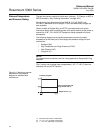
The Rosemount 5300 Series Prior-Use option must be tested at regular
intervals to confirm that the overfill and empty tank protection function result in
the desired system response. The required proof test intervals are dependant
on the configuration of the transmitter and the process environment. The
Rosemount 5300 is designed to have a 5-year proof test interval assuming it
represents the typical 35% of the SIF PFD
AVG
. However, it is the responsibility
of the operator/owner of the system to determine the sufficient time interval
and verify it is followed. See the FMEDA report for additional details or
references.
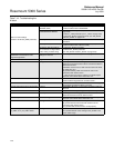
(1) In certain cases, the transmitter does not go into the user defined alarm state. For example,
in case of a short circuit, the transmitter goes into High Alarm state even if Low Alarm has
been configured.
Rosemount Alarm Level
Normal Operation
3.75 mA
(1)
(1) Transmitter Failure, hardware or software alarm in Low position.
4 mA 21.75 mA
(2)
3.9 mA
low saturation
20.8 mA
high saturation
Namur Alarm Level
Normal Operation
3.6 mA
(1)
4 mA 22.5 mA
(2)
(2) Transmitter Failure, hardware or software alarm in High position.
3.8 mA
low saturation
20.5 mA
high saturation
20 mA
20 mA