


Reference Manual
00809-0100-4530, Rev BA
July 2009
Rosemount 5300 Series
8-4
NOTE!
The Rosemount 5300 transmitter is not safety-rated during maintenance
work, configuration changes, multidrop, loop test, or other activity that affects
the Safety Function. Alternative means should be used to ensure process
safety during such activities.
FUNCTIONAL
SPECIFICATIONS
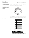
The Safety Function is based on the analog output 4-20 mA, used as the
safety variable. It is configured to activate the alarm function if an error occurs
or if the measured value goes beyond the measurement range set by the
user.
Only the 4-20 mA output can be used in the Safety Function. The HART
protocol can only be used for setup, calibration, and diagnostic purposes, not
for safety critical operation. The measurement signal used by the logic solver
must be the analog 4-20 mA signal proportional to the level generated.
INSTALLATION The device should be installed and configured as a level sensing device per
manufacturer’s instructions. The materials must be compatible with process
conditions and process fluids. No special installation is required in addition to
the standard installation practices outlined in this document.
Environmental limits are available in Appendix A: Reference Data.
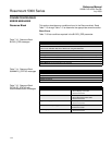
The loop must be designed so the terminal voltage does not drop below the
minimum input voltage, see values in Table 8-2, when the transmitter output is
22.5 mA.
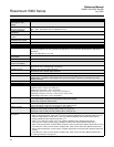
Table 8-2. Minimum input
voltage (U
i
) at different currents
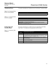
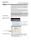
CONFIGURATION Use a HART-compliant master, such as Rosemount Radar Master or 375
Field Communicator, to communicate with and verify configuration of the
Rosemount 5300. A full review of configuration methods is available in
Section 5: Configuration. These instructions are applicable to the 5300
Prior-Use option with any differences noted.
Damping User adjusted damping will affect the transmitter’s ability to respond to
process changes. Therefore, the damping values + response time should not
exceed the loop requirements. For further information on damping, see “Echo
Tracking” on page C-12.
Hazardous
approval
Current
3.60 mA 3.75 mA 21.75 mA 22.50 mA
Minimum input voltage (U
I
)
Non-Hazardous
Installations and
Intrinsically Safe
Installations
16 Vdc 16 Vdc 11 Vdc 11 Vdc
Explosion-proof /
Flameproof
Installations
20 Vdc 20 Vdc 15.5 Vdc 15.5 Vdc