


Reference Manual
00809-0100-4530, Rev BA
July 2009
F-3
Rosemount 5300 Series
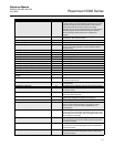
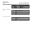
BLOCK_ALM 8 The block alarm is used for all configuration, hardware,
connection failure or system problems in the block. The cause
of the alert is entered in the subcode field. The first alert to
become active will set the Active status in the Status
parameter. As soon as the Unreported status is cleared by the
alert reporting task, another block alert may be reported
without clearing the Active status, if the subcode has
changed.
TRANSDUCER_DIRECTORY 9 Directory that specifies the number and starting indices of the
transducers in the transducer block.
TRANSDUCER_TYPE 10 Identifies the transducer.
XD_ERROR 11 A transducer block alarm subcode.
COLLECTION_DIRECTORY 12 A directory that specifies the number, starting indices, and DD
Item ID’s of the data collections in each transducer within a
transducer block.
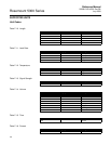
RADAR_LEVEL_TYPE 13 Not used
RADAR_LEVEL 14 Level
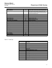
RADAR_LEVEL_RANGE 15 See Table J-4
RADAR_ULLAGE 16 Distance (Ullage)
RADAR_LEVELRATE 17 Level Rate
RADAR_LEVELRATE_RANGE 18 See Table J-5
RADAR_LEVEL_SIGNAL_STRENGTH 19 Signal strength
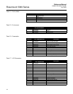
RADAR_LEVEL_SIGNAL_STRENGTH_RANGE 20 See Table J-7
RADAR_VOLUME 21 Volume
RADAR_VOLUME_RANGE 22 See Table J-8
RADAR_INTERNAL_TEMPERATURE 23 Internal Temperature
RADAR_INTERNAL_TEMPERATURE_
RANGE
24 Range, unit and number of decimals
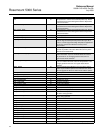
VOLUME_UPPER 25 The calculated volume value of the upper product at the
current level and interface
VOLUME_LOWER 26 The calculated volume value of the lower product at the
current interface
INTERFACE_DISTANCE 27 The distance to the interface (from the upper reference point).
UPPER_PRODUCT_THICKNESS 28 The thickness of the upper product (from the surface value to
the interface value).
INTERFACE_LEVEL 29 The current interface level value (from the zero level reference
point and up to the interface).
INTERFACE_LEVELRATE 30 The current velocity at which the interface is moving. A
positive value indicates the interface is moving up.
INTERFACE_SIGNAL_STRENGTH 31 The current signal strength of the interface echo.
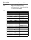
PROBE_TYPE 32 Select the type of probe that is mounted to this
device. Use User Defined probe if your probe can not be
found in the list or if you have done modifications to a
standard probe.
PROBE_LENGTH 33 Enter the length of the probe measured from the
device's upper reference point (normally the upper side of the
tank flange) down to the probe end. If a weight is used it shall
not be included in the length.
PROBE_ANGLE 34 Defines the angle compared to the plumb line at
which the device with probe is mounted (0°means that probe
is mounted vertically).
PROBE_END_PULSE_POLARITY 35 This parameter is used for User Defined probes only. Please
contact Emerson Process Management Service Department
for more information
PROBE_IMPEDANCE 36 This parameter is used for User Defined probes only. Please
contact Emerson Process Management Service Department
for more information
Parameter Index Number Description