


Reference Manual
00809-0100-4530, Rev BA
July 2009
Rosemount 5300 Series
7-8
INTERFACE PULSE NOT
FOUND
In interface applications where the bottom product has a relatively low
dielectric constant (<40), or if the signal is attenuated in the upper product, the
amplitude of the reflected signal is relatively low and difficult for the transmitter
to detect. In such cases, it may be possible to detect the reflected signal if the
corresponding amplitude threshold is adjusted.
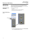
The Rosemount Radar Master (RRM) lets you view a waveform plot to
analyze the measurement signal. The plot shows the signal and the
thresholds used for the different amplitude peaks. By adjusting the Interface
Threshold, it is possible to detect even weak interface signals.
Guidelines for amplitude threshold settings:
• The Interface Threshold should be approximately 50% of the interface
signal amplitude.
• If possible, the Interface Threshold should be higher than the Surface
Threshold.
You can use the RRM software or a 375 Field Communicator to change the
amplitude thresholds. See “Using the Echo Curve Analyzer” on page 7-10 for
more information.
If the Lower Product Dielectric Constant is known, the corresponding
configuration parameter can be changed as an alternative to adjusting the
amplitude thresholds. See also “Dielectric Constant Settings” on page C-14.
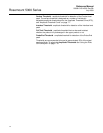
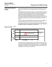
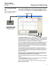
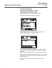
Figure 7-6 illustrates a situation where the Interface Threshold is too high.
The signal amplitude peak at the interface between the upper and lower
products is not detected in this case.
Figure 7-6. Echo Curve plot
indicating that the amplitude
threshold for the interface peak
is too high.
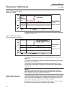
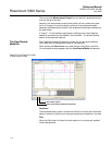
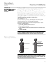
By adjusting the Interface Threshold, the peak at the interface between the
upper and lower products is detected as illustrated in Figure 7-7:
3.0 5.0
The Interface Threshold is above
the interface peak
Amplitude, mV
Distance, m
Interface Threshold
Surface Threshold
Reference Threshold