


Reference Manual
00809-0100-4530, Rev BA
July 2009
Rosemount 5300 Series
8-6
If the overfill and empty tank protection function cannot be tested by a
controlled filling to the response height, suitable simulation of the level or of
the physical measuring effect, e.g. by shorting the probe, must be used to
make the level sensor respond.
The following proof test is recommended. If an error is found in the safety
functionality, the measuring system must be switched out of service and the
process held in a safe state by means of other measures. Proof test results
and corrective actions taken must be documented at
www.emersonprocess.com/rosemount/safety.
Proof test
This test detects approximately 95% of the possible Dangerous Undetected
(DU) failures of the transmitter including the sensor element, not detected by
the transmitter’s automatic diagnostics. Instructions for performing the proof
test with the 375 Field Communicator, Rosemount Radar Master, or AMS, are
available in Appendix E: Performing Proof Test. Note that prior to this test, the
echo curve should be inspected to ensure that no disturbing echoes affecting
the measurement performance are present in the tank.
Required Tools: HART host/communicator and mA meter.
1. Bypass the logic solver or take other appropriate actions to avoid false
trip.
2. Disable write protection if the function is enabled.
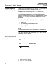
3. Using Loop Test, enter the mA value representing a high alarm current
output and verify that the analog current reaches that value using the
reference meter.
This step tests for compliance voltage problems, such as low loop power
supply voltage or increased wiring resistance.
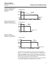
4. Using Loop Test, enter the mA value representing a low alarm current
output and verify that the analog current reaches that value using the
reference meter.
This step tests for possible quiescent current related failures.
5. Perform a two-point calibration check of the transmitter by applying the
level to two points on the probe within the measuring range
(1)
. Verify that
the current output corresponds to the level input values using a known
reference measurement.
This step verifies that the analog output is correct in the operating range
and that the Primary Variable is properly configured.
6. Enable write protection.
7. Restore the loop to full operation.
8. Remove the bypass from the safety logic solver or otherwise restore
normal operation.
9. Document the test result for future reference.
For troubleshooting the transmitter, see “Service and Troubleshooting” on
page 7-1.
(1) For best performance, use the 4 - 20 mA range points as calibration points.