


Reference Manual
00809-0100-4530, Rev BA
July 2009
4-7
Rosemount 5300 Series
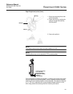
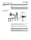
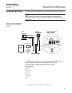
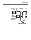
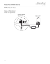
Intrinsically Safe Output For intrinsically safe installations wire the transmitter as shown in Figure 4-6.
NOTE!
Make sure the instruments in the loop are installed in accordance with
intrinsically safe field wiring practices and System Control Drawings when
applicable.
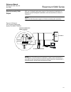
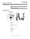
Figure 4-6. Wiring diagram for
intrinsically safe installations
(HART).
For HART communication, a minimum load resistance of 250 within the
loop is required. For maximum load resistance see Figure 4-3.
The power supply voltage ranges from 16 Vdc to 30 Vdc.
IS parameters
(1)
Ui=30 V.
Ii=130 mA.
Pi=1 W.
Ci=7.26 nF.
Li=0.
Load Resistance
Power
Supply
375 Field
Communicator
Rosemount 5300 Series
Radar Transmitter
HART modem
RRM
AMS Suite
250
Approved IS Barrier
(1) See Section B: Product Certifications for more information.