


Reference Manual
00809-0100-4530, Rev BA
July 2009
E-3
Rosemount 5300 Series
ROSEMOUNT RADAR
MASTER (RRM)
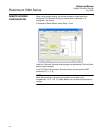
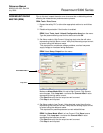
Prior to this test, inspect the echo curve to ensure that no disturbing echoes
affecting the measurement performance are present.
RRM: Tools / Echo Curve
1. Bypass the safety PLC or take other appropriate actions to avoid false
trip.
2. Disable write protection if the function is enabled.
RRM: Select Tools, Lock / Unlock Configuration Area from the menu.
Type the password being used for this device and click OK.
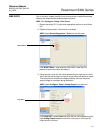
3. Set Alarm mode to High Current. Using loop test, enter the mA value
representing the high alarm current. Verify that the analog output current
is correct using the reference meter.
This step tests for compliance voltage problems, such as low power
supply voltage or increased wiring resistance.
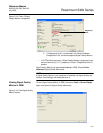
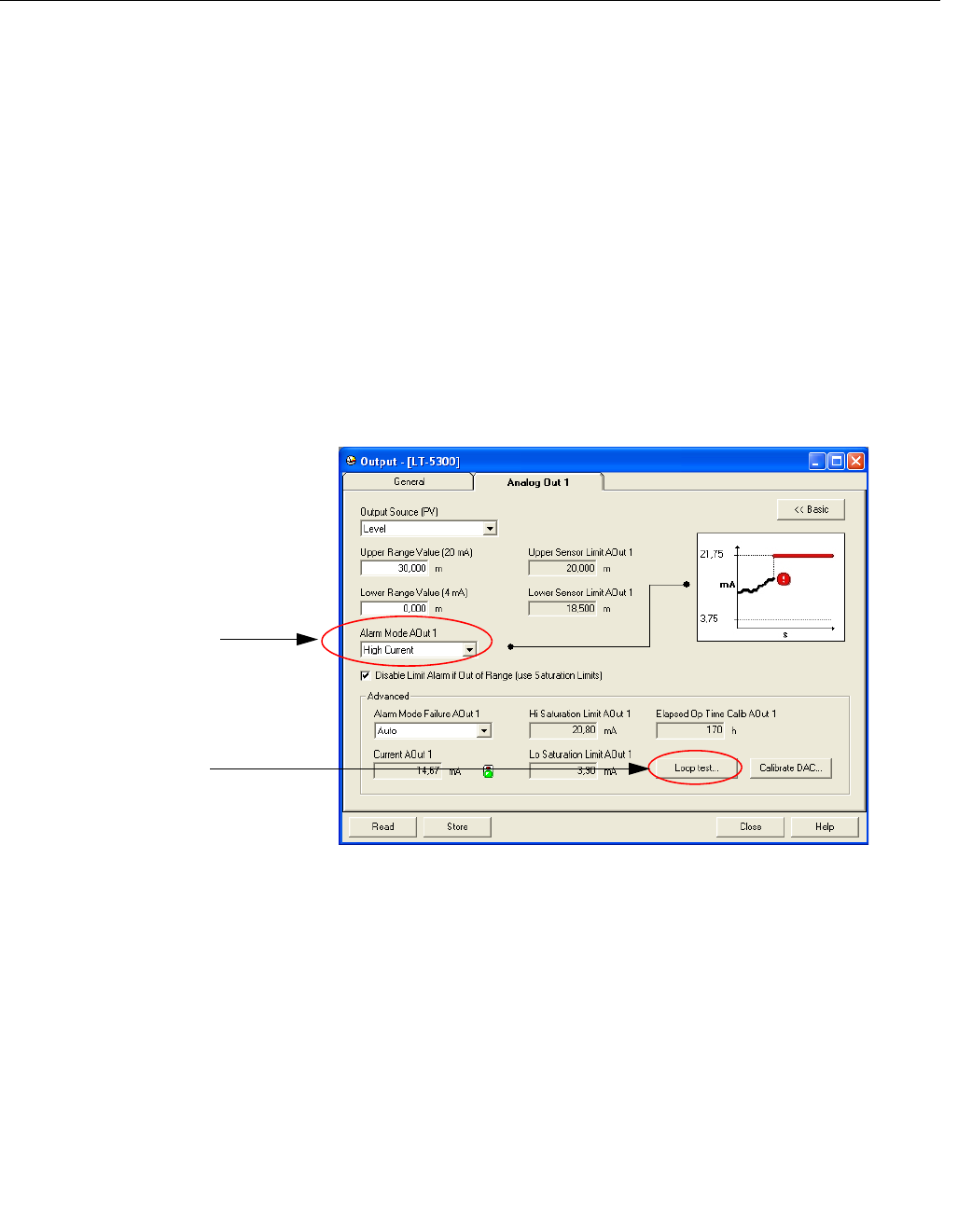
RRM: Select Setup, Output from the menu.
Make sure Alarm Mode AOut 1 is set to High Current. Click Store to
save changes. Click Loop test... and enter the Current AOut 1 value
representing the high alarm current.
Click Start and verify that the output current is correct.
Click Stop to end loop test.
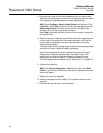
4. Set Alarm mode to Low Current. Using loop test, enter the mA value
representing the low alarm current. Verify that the analog output current
is correct using the reference meter.
This step tests for possible quiescent current related failures.
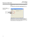
RRM: Set Alarm Mode AOut 1 to Low Current. Click Store to save
changes. Click Loop test... and enter the Current AOut 1 value
representing the low alarm current.
Click Start and verify that the output current is correct.
Click Stop to end loop test.
Alarm Mode AOut 1
Loop test...