


Reference Manual
00809-0100-4530, Rev BA
July 2009
Rosemount 5300 Series
A-4
Process Temperature
and Pressure Rating
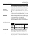
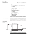
The tank connection consists of a tank seal, a flange
(1)
, Tri-Clamp
(2)
or NPT or
BSP/G threads
(3)
. See “Ordering Information” on page A-21).
Flange mating face dimensions follow ANSI B 16.5, JIS B2220, and
EN 1092-1 standards for blind flanges. Fisher and Masoneilan flanges are
also available.
Certain models of flanged Alloy and PTFE covered probes have a tank
connection design with a protective plate of the same material as the probe, to
prevent the 316L / EN 1.4404 SST flange from being exposed to the tank
atmosphere.
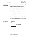
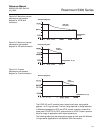
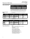
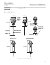
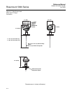
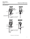
The following diagrams give process temperature (maximum product
temperature at the lower part of the flange) and pressure ratings for tank
connections:
• Standard (Std)
• High Temperature and High Pressure (HTHP)
• High Pressure (HP)
• Cryogenic (C)
NOTE!
For standard tank connection, the final rating depends on flange and O-ring
selection.
The C version can manage lower temperatures (-321 °F/-196 °C) than the
Standard, HP, and HTHP versions.
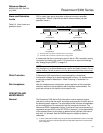
Figure A-1. Maximum process
temperature and pressure
diagram for standard tank
connections.
(1) EN (DIN), ANSI, Fisher or Masoneilan.
(2) 1.5, 2, 3 or 4 in. for Single Lead probes.
(3) 1, 1.5, or 2 in. depending on probe type
Temperature °F (°C)
Pressure psig (bar)
PTFE covered probe and
flange (model code 7)