


Reference Manual
00809-0100-4530, Rev BA
July 2009
Rosemount 5300 Series
E-4
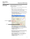
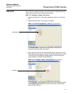
5. Restore the Alarm mode to the original mode used in the loop. Verify that
the analog output current is correct.
RRM: Set Alarm Mode AOut 1 to original mode. Click Store to save
changes.
Verify that the output current is correct.
6. Perform a two-point calibration check of the transmitter by applying level
to two points on the probe within the measuring range. Verify that the
current output corresponds to the level input values using a known
reference measurement.
This step verifies that the analog output is correct in the operating range
and that the Primary Variable is properly configured.
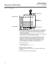
Note that the applied level has to be between the Upper and Lower
Range values, otherwise the transmitter enters alarm mode. If the
applied level is outside the Maximum Measuring Range, the level
reading accuracy may be reduced. For best performance, use the
4-20 mA range points as calibration points. See Figure E-1 on page E-2.
7. Enable write protection.
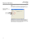
RRM: Select Tools, Lock / Unlock Configuration Area from the menu.
8. Restore the loop to full operation.
9. Remove the bypass from the safety PLC or otherwise restore normal
operation.
10. Document the test results for future reference.