


Reference Manual
00809-0100-4530, Rev BA
July 2009
2-7
Rosemount 5300 Series
SYSTEM
ARCHITECTURE
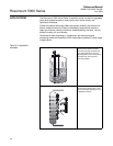
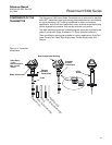
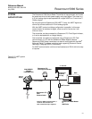
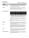
The Rosemount 5300 Series Radar Transmitter is loop-powered, and it uses
the same two wires for both power supply and output signal. The output is a
4-20 mA analog signal superimposed with a digital HART
®
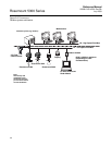
or FOUNDATION™
Fieldbus signal.
By using the optional Rosemount 333 HART Tri-loop, the HART signal can
convert up to three additional 4-20 mA analog signals.
With the HART protocol multidrop configuration is possible. In this case,
communication is restricted to digital, since current is fixed to the 4 mA
minimum value.
The transmitter can be connected to a Rosemount 751 Field Signal Indicator,
or it can be equipped with an integral display.
The transmitter can easily be configured using a Rosemount 375 Field
Communicator or a PC with the Rosemount Radar Master software.
Rosemount 5300 Series transmitters can also be configured with the AMS
®
Suite and DeltaV™ software, and other tools supporting Electronic Device
Description Language (EDDL) functionality.
For HART communication a minimum load resistance of 250 within the loop
is required.
Figure 2-5. HART system
architecture
4-20 mA/HART
Rosemount 751
Field Signal Indicator
Rosemount 375
Field
Communicator
HART modem
5300 SERIES
RADAR
TRANSMITTER
DCS
Rosemount
333 HART
Tri-Loop
3 x 4-20 mA
Rosemount Radar Master
or
AMS Suite
Integral
Display
Note! For HART communication, a
minimum load resistance of
250 within the loop is required.