


Reference Manual
00809-0100-4530, Rev BA
July 2009
Rosemount 5300 Series
5-4
BASIC CONFIGURATION
PARAMETERS
This section describes basic configuration parameters for a Rosemount 5300
transmitter. Basic configuration is only needed for the 5300 Series
transmitters which are not pre-configured at the factory. Factory configuration
is normally specified in the Configuration Data Sheet.
Measurement Units Measurement units can be specified for presentation of Level/Interface Level,
Level Rate, Volume, and Temperature values.
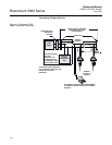
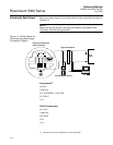
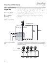
Tank and Probe
Geometry
The basic transmitter configuration includes setting the tank geometry
parameters.
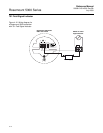
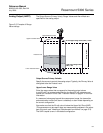
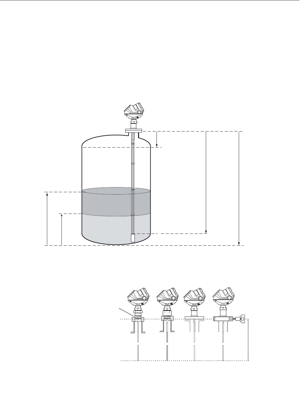
Figure 5-1. Tank Geometry
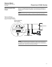
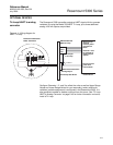
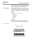
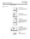
Figure 5-2. Upper Reference
Point
For the different tank connections the Upper Reference Point is located at the
underside of the threaded adapter or at the underside of the welded flange, as
illustrated in Figure 5-2:
Tank Height
Hold Off/
Upper Null Zone
Product Level
Upper Reference Point
Lower Reference Point
Interface
Level
Probe
Length
NPT BSP (G) Flange
Upper Reference Point
Adapter
Tri-Clamp