


Reference Manual
00809-0100-4530, Rev BA
July 2009
Rosemount 5300 Series
C-8
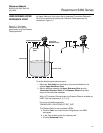
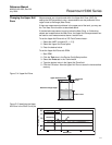
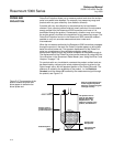
THRESHOLD SETTINGS Measurement with the Rosemount 5300 is based on the fact that the radar
signal pulses are reflected by the product surface and the interface between
two liquids. Various signal amplitude thresholds are used to separate the
measurement signal from disturbing echoes and noise. Normally, the
amplitude thresholds are automatically set by the 5300 transmitter, and no
manual settings are needed. However, due to the properties of the product, it
may in rare cases be necessary to adjust the amplitude thresholds for
optimum measurement performance. RRM supports threshold settings in the
Advanced Configuration window:
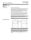
1. Click the Advanced icon in the Device Config/Setup toolbar.
2. Select the Thresholds tab in the Advanced Configuration window.
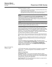
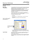
Figure C-6. Threshold settings in
RRM.
Automatic threshold settings are enabled by default. In the Advanced
Configuration window the Interface, Reference, Probe End and Full Tank
thresholds can also be set manually.
Automatic Surface Threshold
When this check-box is selected, the transmitter automatically sets the
Surface threshold to a constant value based on the configured Dielectric
Constant of the product.
Note that by enabling the Automatic Surface threshold setting, the Amplitude
Threshold Curve (ATC) is replaced by a constant threshold value. See “Using
the Echo Curve Analyzer” on page 7-10 for more information on how to use
the ATC.
The Surface threshold can also be manually set by using the Set Threshold
function in the Echo Curve Analyzer/Configuration Mode window (see “The
Configuration Mode Tab” on page 7-11).
Interface Threshold
Amplitude threshold for detection of the Interface level peak.